

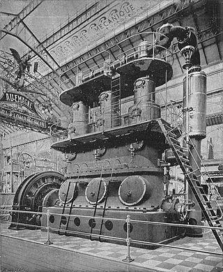
High-speed steam engines were one of the final developments of the stationary steam engine. They ran at a high speed, of several hundred rpm, [1] which was needed by tasks such as electricity generation. [2]
High-speed steam engines were one of the final developments of the stationary steam engine. They ran at a high speed, of several hundred rpm, [1] which was needed by tasks such as electricity generation. [2]

They have two primary characteristics:
These also resulted in a number of secondary characteristics. Although these were not defining to the type, or were always the case, they were recognisably common:
High speed was not needed for electrical power generation in the largest citywide plants. [lower-roman 2] As these plants were necessarily large, they could also use large-diameter dynamos with many pole pieces. This gave the necessary linear speed (in poles passed / time) for a lower rotational shaft speed.
These engines were produced with either simple or compound operating cycles. Smaller examples were usually simple, as the difficulties of achieving good regulation outweighed the efficiencies of compounding. High-speed engines did develop a reputation for profligacy. [1] For larger engines the fuel cost savings were worthwhile and compound designs such as the Willans engine were used.
They also used a wide range of valves. Examples with either slide or piston valves were common. Multi-cylinder single-acting engines typically shared one piston valve between two cylinders, either between the cylinders or horizontally above them. [1]
The valvegear driving these valves was usually simple, a single eccentric designed only to run at one speed, in one direction, for a fairly constant load. Although these engines were contemporaneous with sophisticated and efficient valvegears such as the Corliss, these trip valves were incapable of working quickly enough. [3] [4] [5]


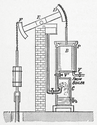
A key requirement for the high-speed steam engine was accurate control of a constant speed, even under a rapidly changing load. Although the control of steam engines via a centrifugal governor dates back to Watt, this control was inadequate. These early governors operated a throttle valve to control the flow of steam to the engine. This gives an inadequately responsive control for the constant speed needed for electricity generation.
The solution developed for high-speed steam engines was the "automatic" governor. Rather than controlling the flow rate of steam, it controlled the timing or 'cut-off' of the inlet valves. [6] [7] This governor was interspersed between the crankshaft and the eccentric driving the valve gear. It was often made as part of the engine's flywheel. A centrifugal bob weight in the governor moved out against a spring with increasing speed. This caused the eccentric's position to shift relative to the crank, changing the valve timing and causing an early cut-off. As this control acted directly at the cylinder port, rather than through a long pipe from a throttle valve, it could be very fast-acting.

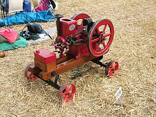
Lubrication of the first high-speed engines, such as the Ideal (an open-crank horizontal engine), [8] were lubricated by a development of the oil cup systems previously widespread on medium-speed stationary engines. Oil cups and multi-point lubricators could oil shaft bearings well enough and a single sight-glass could be observed by even the most careless engine driver or oiler. The difficulty was that on high-speed engines, oilers could no longer be mounted on moving parts, such as the crosshead or connecting rod. Any oil reservoir here would be churned around by the movement and such a necessarily small reserve might also be inadequate incapacity for an engine doing so much work in a small space. More care was thus given to the thoroughness of oiling, and moving parts such as the crankpin were fed by drillings through the crankshaft from oil supplies that were rotating but not moving, such as the main bearings. Centrifugal force was also used to distribute the oil. [8] It was usual that high-speed engines would have only one or two lubricators, [lower-roman 3] so that engine tending was a simpler task and less prone to breakdowns from simple carelessness and running a lubricator dry.

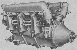
As speeds increased, the high-speed engine evolved towards its developed form of the multi-cylinder vertical engine with an enclosed crankcase. There was also a tendency to use single-acting pistons. This had two advantages, the lubrication could be provided by a generous 'splash' system within the crankcase that also helped with cooling, and secondly that the forces in a single-acting engine always act in the same way, as a compression force along the piston rod and connecting rod. This meant that even if a bearing's clearances were relatively slack, the bearing was always held tight. Slack, and thus free-running, bearings could be accepted. An example of such an engine would be the twin-cylinder Westinghouse engines. [9] These engines used a trunk piston, as used for internal combustion engines today, where there is no separate crosshead and the gudgeon pin of the connecting rod is moved up within the piston itself. This provides a very compact layout, but obviously requires a single-acting piston. The main crankshaft bearings of this engine were provided with separate oilers that drained into the crankcase sump. It was recognised that the crankcase oil would become contaminated with water from condensed steam and blow-by from the pistons. A valve was provided for draining this collected condensate off from beneath the oil in the bottom of the deep sump.
The important concept of pressure lubrication of engine bearings began with high-speed steam engines and is now a vital part of internal combustion engines. This is both reliable as a lubrication system and also allows the use of hydrostatic bearings ('oil wedge') that can support greater loads. The first patents for this were issued to Belliss & Morcom in 1890, from the work of their draughtsman Albert Charles Pain. [3] Belliss & Morcom preferred double-acting cylinders, so as to produce the smallest possible engines for a given power; one of their major markets, like Peter Brotherhood, was in supplying generator sets to the Royal Navy for use in the confines of a warship engine room. The difficulty of a double-acting engine was that the direction of the forces in the connecting rod now reverses between compression and tension, so that the bearing clearances must be made tighter to avoid any rattling. Belliss and Morcom developed a two-cylinder engine of 20 bhp at 625 rpm that used a small separate oil pump to feed oil under pressure to the crank bearings, through long drilled holes in the crankshaft. This provided reliable lubrication and cooling and the pressure of the oil film was sufficient to allow the use of double-acting engines with adequate clearance to provide free running. [10]

A piston is a component of reciprocating engines, reciprocating pumps, gas compressors, hydraulic cylinders and pneumatic cylinders, among other similar mechanisms. It is the moving component that is contained by a cylinder and is made gas-tight by piston rings. In an engine, its purpose is to transfer force from expanding gas in the cylinder to the crankshaft via a piston rod and/or connecting rod. In a pump, the function is reversed and force is transferred from the crankshaft to the piston for the purpose of compressing or ejecting the fluid in the cylinder. In some engines, the piston also acts as a valve by covering and uncovering ports in the cylinder.
A two-strokeengine is a type of internal combustion engine that completes a power cycle with two strokes of the piston during one power cycle, this power cycle being completed in one revolution of the crankshaft. A four-stroke engine requires four strokes of the piston to complete a power cycle during two crankshaft revolutions. In a two-stroke engine, the end of the combustion stroke and the beginning of the compression stroke happen simultaneously, with the intake and exhaust functions occurring at the same time.

A connecting rod, also called a 'con rod', is the part of a piston engine which connects the piston to the crankshaft. Together with the crank, the connecting rod converts the reciprocating motion of the piston into the rotation of the crankshaft. The connecting rod is required to transmit the compressive and tensile forces from the piston. In its most common form, in an internal combustion engine, it allows pivoting on the piston end and rotation on the shaft end.

In a piston engine, the crankcase is the housing that surrounds the crankshaft. In most modern engines, the crankcase is integrated into the engine block.
Within piston engines, a wet sump is part of a lubrication system whereby the crankcase sump is used as an integral oil reservoir. An alternative system is the dry sump, whereby oil is pumped from a shallow sump into an external reservoir.
A hit-and-miss engine or Hit 'N' Miss is a type of stationary internal combustion engine that is controlled by a governor to only fire at a set speed. They are usually 4-stroke but 2-stroke versions were made. It was conceived in the late 19th century and produced by various companies from the 1890s through approximately the 1940s. The name comes from the speed control on these engines: they fire ("hit") only when operating at or below a set speed, and cycle without firing ("miss") when they exceed their set speed. This is as compared to the "throttle governed" method of speed control. The sound made when the engine is running without a load is a distinctive "Snort POP whoosh whoosh whoosh whoosh snort POP" as the engine fires and then coasts until the speed decreases and it fires again to maintain its average speed. The snorting is caused by the atmospheric intake valve used on many of these engines.

The oil pump is an internal combustion engine part that circulates engine oil under pressure to the rotating bearings, the sliding pistons and the camshaft of the engine. This lubricates the bearings, allows the use of higher-capacity fluid bearings and also assists in cooling the engine.

A ring oiler or oil ring is a form of oil-lubrication system for bearings.
The Lorraine 12H Pétrel was a French V-12 supercharged, geared piston aeroengine initially rated at 370 kW (500 hp), but later developed to give 640 kW (860 hp). It powered a variety of mostly French aircraft in the mid-1930s, several on an experimental basis.
In mechanical engineering, the cylinders of reciprocating engines are often classified by whether they are single- or double-acting, depending on how the working fluid acts on the piston.

The Austin 25-30 is a motor car. It was the first automobile produced by newly established British car manufacturer Austin.

A total-loss oiling system is an engine lubrication system whereby oil is introduced into the engine, and then either burned or ejected overboard. Now rare in four-stroke engines, total loss oiling is still used in many two-stroke engines.

An internal combustion engine is a heat engine in which the combustion of a fuel occurs with an oxidizer in a combustion chamber that is an integral part of the working fluid flow circuit. In an internal combustion engine, the expansion of the high-temperature and high-pressure gases produced by combustion applies direct force to some component of the engine. The force is typically applied to pistons, turbine blades, a rotor, or a nozzle. This force moves the component over a distance, transforming chemical energy into kinetic energy which is used to propel, move or power whatever the engine is attached to.
The Willans engine or central valve engine was a high-speed stationary steam engine used mainly for electricity generation around the start of the 20th century.

The Cyclone Waste Heat Engine (WHE) is a small steam engine developed to produce power from steam created from waste heat. It is an offshoot of the development of the Cyclone Mark V Engine by the company Cyclone Power Technologies of Pompano Beach, Florida. The original versions were designed by inventor Harry Schoell, founder of Cyclone Power Technologies and the later versions have been designed by the Ohio State University Center for Automotive Research (OSU-CAR).

Their new Daimler 22 horsepower full-size luxury car was first displayed by Daimler in April 1902 at The Automobile Club’s Exhibition in London's Agricultural Hall. Daimler had elected to drop their multiple old low powered designs and restrict themselves to this 22 horsepower and a pair of 9 or 12 horsepower cars to the same design as the 22 but more lightly constructed. The King’s not quite finished new Daimler 22 was reported to be the chief attraction of the show.

The MWM AKD 112 Z is an air-cooled two-cylinder inline diesel engine produced by MWM from 1955 – 1960. One, three and four cylinder variants of the same engine family were also produced by MWM.

The 4 VD 14,5/12-1 SRW is an inline four-cylinder diesel engine produced by the VEB IFA Motorenwerke Nordhausen from 1967 to 1990. The engine was one of the standard modular engines for agricultural and industrial use in the Comecon-countries. Approximately one million units were made.
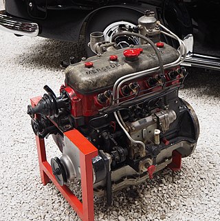
The Mercedes-Benz OM 138 is a diesel engine manufactured by Daimler-Benz. In total, 5,719 units were produced between 1935 and 1940. It was the first diesel engine especially developed and made for a passenger car. The first vehicle powered by the OM 138 was the Mercedes-Benz W 138. The light Mercedes-Benz trucks L 1100 and L 1500 as well as the bus O 1500 were also offered with the OM 138 as an alternative to the standard Otto engine.

The De Dion-Bouton 130 hp aircraft engine, also referred to as De Dion-Bouton 12B, was a twelve-cylinder, air cooled vee aircraft engine that has been built by De Dion-Bouton.
{{cite book}}: |work= ignored (help), 400 to 1,200 rpm