Each x86 assembly instruction is represented by a mnemonic which, often combined with one or more operands, translates to one or more bytes called an opcode; the NOP instruction translates to 0x90, for instance, and the HLT instruction translates to 0xF4.[3] There are potential opcodes with no documented mnemonic which different processors may interpret differently, making a program using them behave inconsistently or even generate an exception on some processors. These opcodes often turn up in code writing competitions as a way to make the code smaller, faster, more elegant or just show off the author's prowess.
Syntax
x86 assembly language has two main syntax branches: Intel syntax and AT&T syntax.[6] Intel syntax is dominant in the DOS and Windows world, and AT&T syntax is dominant in the Unix world, since Unix was created at AT&T Bell Labs.[7] Here is a summary of the main differences between Intel syntax and AT&T syntax:
AT&T
Intel
Parameter order
movl$5,%eax
Source before the destination.
moveax,5
Destination before source.
Parameter size
addl$0x24,%espmovslq%ecx,%raxpaddd%xmm1,%xmm2
Mnemonics are suffixed with a letter indicating the size of the operands: q for qword (64 bits), l for long (dword, 32 bits), w for word (16 bits), and b for byte (8 bits).[6]
addesp,24hmovsxdrax,ecxpadddxmm2,xmm1
Derived from the name of the register that is used (e.g. rax, eax, ax, al imply q, l, w, b, respectively).
Width-based names may still appear in instructions when they define a different operation.
MOVSXD refers to sign extension with dword input, unlike MOVSX.
SIMD registers have width-named instructions that determine how to split up the register. AT&T tends to keep the names unchanged, so PADDD is not renamed to "paddl".
Arithmetic expressions in square brackets; additionally, size keywords like byte, word, or dword have to be used if the size cannot be determined from the operands.[6]
Many x86 assemblers use Intel syntax, including FASM, MASM, NASM, TASM, and YASM. GAS, which originally used AT&T syntax, has supported both syntaxes since version 2.10 via the .intel_syntax directive.[6][8][9] A quirk in the AT&T syntax for x86 is that x87 operands are reversed, an inherited bug from the original AT&T assembler.[10]
The AT&T syntax is nearly universal to all other architectures (retaining the same mov order); it was originally a syntax for PDP-11 assembly. The Intel syntax is specific to the x86 architecture, and is the one used in the x86 platform's documentation. The Intel 8080, which predates the x86, also uses the "destination-first" order for mov.[11]
x86 processors have a collection of registers available to be used as stores for binary data. Collectively the data and address registers are called the general registers. Each register has a special purpose in addition to what they can all do:[3]
segment registers (CS, DS, ES, FS, GS, SS) which determine where a 64k segment starts (no FS & GS in 80286 & earlier)
extra extension registers (MMX, 3DNow!, SSE, etc.) (Pentium & later only).
The IP register points to the memory offset of the next instruction in the code segment (it points to the first byte of the instruction). The IP register cannot be accessed by the programmer directly.
The x86 registers can be used by using the MOV instructions. For example, in Intel syntax:
movax,1234h; copies the value 1234hex (4660d) into register AX
movbx,ax; copies the value of the AX register into the BX register
Segmented addressing
The x86 architecture in real and virtual 8086 mode uses a process known as segmentation to address memory, not the flat memory model used in many other environments. Segmentation involves composing a memory address from two parts, a segment and an offset; the segment points to the beginning of a 64 KiB (64×210) group of addresses and the offset determines how far from this beginning address the desired address is. In segmented addressing, two registers are required for a complete memory address. One to hold the segment, the other to hold the offset. In order to translate back into a flat address, the segment value is shifted four bits left (equivalent to multiplication by 24 or 16) then added to the offset to form the full address, which allows breaking the 64k barrier through clever choice of addresses, though it makes programming considerably more complex.
In real mode/protected only, for example, if DS contains the hexadecimal number 0xDEAD and DX contains the number 0xCAFE they would together point to the memory address 0xDEAD * 0x10 + 0xCAFE == 0xEB5CE. Therefore, the CPU can address up to 1,048,576 bytes (1 MB) in real mode. By combining segment and offset values we find a 20-bit address.
The original IBM PC restricted programs to 640 KB but an expanded memory specification was used to implement a bank switching scheme that fell out of use when later operating systems, such as Windows, used the larger address ranges of newer processors and implemented their own virtual memory schemes.
Protected mode, starting with the Intel 80286, was utilized by OS/2. Several shortcomings, such as the inability to access the BIOS and the inability to switch back to real mode without resetting the processor, prevented widespread usage.[12] The 80286 was also still limited to addressing memory in 16-bit segments, meaning only 216 bytes (64 kilobytes) could be accessed at a time. To access the extended functionality of the 80286, the operating system would set the processor into protected mode, enabling 24-bit addressing and thus 224 bytes of memory (16 megabytes).
In protected mode, the segment selector can be broken down into three parts: a 13-bit index, a Table Indicator bit that determines whether the entry is in the GDT or LDT and a 2-bit Requested Privilege Level; see x86 memory segmentation.
When referring to an address with a segment and an offset the notation of segment:offset is used, so in the above example the flat address 0xEB5CE can be written as 0xDEAD:0xCAFE or as a segment and offset register pair; DS:DX.
There are some special combinations of segment registers and general registers that point to important addresses:
CS:IP (CS is Code Segment, IP is Instruction Pointer) points to the address where the processor will fetch the next byte of code.
SS:SP (SS is Stack Segment, SP is Stack Pointer) points to the address of the top of the stack, i.e. the most recently pushed byte.
SS:BP (SS is Stack Segment, BP is Stack Frame Pointer) points to the address of the top of the stack frame, i.e. the base of the data area in the call stack for the currently active subprogram.
DS:SI (DS is Data Segment, SI is Source Index) is often used to point to string data that is about to be copied to ES:DI.
ES:DI (ES is Extra Segment, DI is Destination Index) is typically used to point to the destination for a string copy, as mentioned above.
The Intel 80386 featured three operating modes: real mode, protected mode and virtual mode. The protected mode which debuted in the 80286 was extended to allow the 80386 to address up to 4 GB of memory, the all new virtual 8086 mode (VM86) made it possible to run one or more real mode programs in a protected environment which largely emulated real mode, though some programs were not compatible (typically as a result of memory addressing tricks or using unspecified op-codes).
The 32-bit flat memory model of the 80386's extended protected mode may be the most important feature change for the x86 processor family until AMD released x86-64 in 2003, as it helped drive large scale adoption of Windows 3.1 (which relied on protected mode) since Windows could now run many applications at once, including DOS applications, by using virtual memory and simple multitasking.
The x86 processors support five modes of operation for x86 code, Real Mode, Protected Mode, Long Mode, Virtual 86 Mode, and System Management Mode, in which some instructions are available and others are not. A 16-bit subset of instructions is available on the 16-bit x86 processors, which are the 8086, 8088, 80186, 80188, and 80286. These instructions are available in real mode on all x86 processors, and in 16-bit protected mode (80286 onwards), additional instructions relating to protected mode are available. On the 80386 and later, 32-bit instructions (including later extensions) are also available in all modes, including real mode; on these CPUs, V86 mode and 32-bit protected mode are added, with additional instructions provided in these modes to manage their features. SMM, with some of its own special instructions, is available on some Intel i386SL, i486 and later CPUs. Finally, in long mode (AMD Opteron onwards), 64-bit instructions, and more registers, are also available. The instruction set is similar in each mode but memory addressing and word size vary, requiring different programming strategies.
The modes in which x86 code can be executed in are:
20-bit segmented memory address space (meaning that only 1 MB of memory can be addressed— actually since 80286 a little more through HMA), direct software access to peripheral hardware, and no concept of memory protection or multitasking at the hardware level. Computers that use BIOS start up in this mode.
Expands addressable physical memory to 16 MB and addressable virtual memory to 1 GB. Provides privilege levels and protected memory, which prevents programs from corrupting one another. 16-bit protected mode (used during the end of the DOS era) used a complex, multi-segmented memory model. 32-bit protected mode uses a simple, flat memory model.
Mostly an extension of the 32-bit (protected mode) instruction set, but unlike the 16–to–32-bit transition, many instructions were dropped in the 64-bit mode. Pioneered by AMD.
A special hybrid operating mode that allows real mode programs and operating systems to run while under the control of a protected mode supervisor operating system
Handles system-wide functions like power management, system hardware control, and proprietary OEM designed code. It is intended for use only by system firmware. All normal execution, including the operating system, is suspended. An alternate software system (which usually resides in the computer's firmware, or a hardware-assisted debugger) is then executed with high privileges.
Switching modes
The processor runs in real mode immediately after power on, so an operating systemkernel, or other program, must explicitly switch to another mode if it wishes to run in anything but real mode. Switching modes is accomplished by modifying certain bits of the processor's control registers after some preparation, and some additional setup may be required after the switch.
Examples
With a computer running legacy BIOS, the BIOS and the boot loader run in Real mode. The 64-bit operating system kernel checks and switches the CPU into Long mode and then starts new kernel-mode threads running 64-bit code.
With a computer running UEFI, the UEFI firmware (except CSM and legacy Option ROM), the UEFI boot loader and the UEFI operating system kernel all run in Long mode.
Variable length and alignment independent (encoded as little endian, as is all data in the x86 architecture)
Mainly one-address and two-address instructions, that is to say, the first operand is also the destination.
Memory operands as both source and destination are supported (frequently used to read/write stack elements addressed using small immediate offsets).
Both general and implicit register usage; although all seven (counting ebp) general registers in 32-bit mode, and all fifteen (counting rbp) general registers in 64-bit mode, can be freely used as accumulators or for addressing, most of them are also implicitly used by certain (more or less) special instructions; affected registers must therefore be temporarily preserved (normally stacked), if active during such instruction sequences.
Produces conditional flags implicitly through most integer ALU instructions.
Supports various addressing modes including immediate, offset, and scaled index but not PC-relative, except jumps (introduced as an improvement in the x86-64 architecture).
Contains special support for atomic read-modify-write instructions (xchg, cmpxchg/cmpxchg8b, xadd, and integer instructions which combine with the lock prefix)
SIMD instructions (instructions which perform parallel simultaneous single instructions on many operands encoded in adjacent cells of wider registers).
Stack instructions
The x86 architecture has hardware support for an execution stack mechanism. Instructions such as push, pop, call and ret are used with the properly set up stack to pass parameters, to allocate space for local data, and to save and restore call-return points. The retsize instruction is very useful for implementing space efficient (and fast) calling conventions where the callee is responsible for reclaiming stack space occupied by parameters.
When setting up a stack frame to hold local data of a recursive procedure there are several choices; the high level enter instruction (introduced with the 80186) takes a procedure-nesting-depth argument as well as a local size argument, and may be faster than more explicit manipulation of the registers (such as push bp; mov bp, sp; sub sp, size). Whether it is faster or slower depends on the particular x86-processor implementation as well as the calling convention used by the compiler, programmer or particular program code; most x86 code is intended to run on x86-processors from several manufacturers and on different technological generations of processors, which implies highly varying microarchitectures and microcode solutions as well as varying gate- and transistor-level design choices.
The full range of addressing modes (including immediate and base+offset) even for instructions such as push and pop, makes direct usage of the stack for integer, floating point and address data simple, as well as keeping the ABI specifications and mechanisms relatively simple compared to some RISC architectures (require more explicit call stack details).
Integer ALU instructions
x86 assembly has the standard mathematical operations, add, sub, neg, imul and idiv (for signed integers), with mul and div (for unsigned integers); the logical operatorsand, or, xor, not; bitshift arithmetic and logical, sal/sar (for signed integers), shl/shr (for unsigned integers); rotate with and without carry, rcl/rcr, rol/ror, a complement of BCD arithmetic instructions, aaa, aad, daa and others.
Floating-point instructions
x86 assembly language includes instructions for a stack-based floating-point unit (FPU). The FPU was an optional separate coprocessor for the 8086 through the 80386, it was an on-chip option for the 80486 series, and it is a standard feature in every Intel x86 CPU since the 80486, starting with the Pentium. The FPU instructions include addition, subtraction, negation, multiplication, division, remainder, square roots, integer truncation, fraction truncation, and scale by power of two. The operations also include conversion instructions, which can load or store a value from memory in any of the following formats: binary-coded decimal, 32-bit integer, 64-bit integer, 32-bit floating-point, 64-bit floating-point or 80-bit floating-point (upon loading, the value is converted to the currently used floating-point mode). x86 also includes a number of transcendental functions, including sine, cosine, tangent, arctangent, exponentiation with the base 2 and logarithms to bases 2, 10, or e.
The stack register to stack register format of the instructions is usually fop st, st(n) or fop st(n), st, where st is equivalent to st(0), and st(n) is one of the 8 stack registers (st(0), st(1), ..., st(7)). Like the integers, the first operand is both the first source operand and the destination operand. fsubr and fdivr should be singled out as first swapping the source operands before performing the subtraction or division. The addition, subtraction, multiplication, division, store and comparison instructions include instruction modes that pop the top of the stack after their operation is complete. So, for example, faddp st(1), st performs the calculation st(1) = st(1) + st(0), then removes st(0) from the top of stack, thus making what was the result in st(1) the top of the stack in st(0).
SIMD instructions
Modern x86 CPUs contain SIMD instructions, which largely perform the same operation in parallel on many values encoded in a wide SIMD register. Various instruction technologies support different operations on different register sets, but taken as complete whole (from MMX to SSE4.2) they include general computations on integer or floating-point arithmetic (addition, subtraction, multiplication, shift, minimization, maximization, comparison, division or square root). So for example, paddw mm0, mm1 performs 4 parallel 16-bit (indicated by the w) integer adds (indicated by the padd) of mm0 values to mm1 and stores the result in mm0. Streaming SIMD Extensions or SSE also includes a floating-point mode in which only the very first value of the registers is actually modified (expanded in SSE2). Some other unusual instructions have been added including a sum of absolute differences (used for motion estimation in video compression, such as is done in MPEG) and a 16-bit multiply accumulation instruction (useful for software-based alpha-blending and digital filtering). SSE (since SSE3) and 3DNow! extensions include addition and subtraction instructions for treating paired floating-point values like complex numbers.
These instruction sets also include numerous fixed sub-word instructions for shuffling, inserting and extracting the values around within the registers. In addition there are instructions for moving data between the integer registers and XMM (used in SSE)/FPU (used in MMX) registers.
Memory instructions
The x86 processor also includes complex addressing modes for addressing memory with an immediate offset, a register, a register with an offset, a scaled register with or without an offset, and a register with an optional offset and another scaled register. So for example, one can encode mov eax, [Table + ebx + esi*4] as a single instruction which loads 32 bits of data from the address computed as (Table + ebx + esi * 4) offset from the ds selector, and stores it to the eax register. In general x86 processors can load and use memory matched to the size of any register it is operating on. (The SIMD instructions also include half-load instructions.)
In principle, because the instruction opcode is separate from the addressing mode byte, those instructions are orthogonal because any of those opcodes can be mixed-and-matched with any addressing mode. However, the x86 instruction set is generally considered non-orthogonal because many other opcodes have some fixed addressing mode (they have no addressing mode byte), and every register is special.[21][22]
The x86 instruction set includes string load, store, move, scan and compare instructions (lods, stos, movs, scas and cmps) which perform each operation to a specified size (b for 8-bit byte, w for 16-bit word, d for 32-bit double word) then increments/decrements (depending on DF, direction flag) the implicit address register (si for lods, di for stos and scas, and both for movs and cmps). For the load, store and scan operations, the implicit target/source/comparison register is in the al, ax or eax register (depending on size). The implicit segment registers used are ds for si and es for di. The cx or ecx register is used as a decrementing counter, and the operation stops when the counter reaches zero or (for scans and comparisons) when inequality is detected. Unfortunately, over the years the performance of some of these instructions became neglected and in certain cases it is now possible to get faster results by writing out the algorithms yourself. Intel and AMD have refreshed some of the instructions though, and a few now have very respectable performance, so it is recommended that the programmer should read recent respected benchmark articles before choosing to use a particular instruction from this group.
The stack is a region of memory and an associated ‘stack pointer’, which points to the bottom of the stack. The stack pointer is decremented when items are added (‘push’) and incremented after things are removed (‘pop’). In 16-bit mode, this implicit stack pointer is addressed as SS:[SP], in 32-bit mode it is SS:[ESP], and in 64-bit mode it is [RSP]. The stack pointer actually points to the last value that was stored, under the assumption that its size will match the operating mode of the processor (i.e., 16, 32, or 64 bits) to match the default width of the push/pop/call/ret instructions. Also included are the instructions enter and leave which reserve and remove data from the top of the stack while setting up a stack frame pointer in bp/ebp/rbp. However, direct setting, or addition and subtraction to the sp/esp/rsp register is also supported, so the enter/leave instructions are generally unnecessary.
This code is the beginning of a function typical for a high-level language when compiler optimisation is turned off for ease of debugging:
pushrbp; Save the calling function’s stack frame pointer (rbp register)movrbp,rsp; Make a new stack frame below our caller’s stacksubrsp,32; Reserve 32 bytes of stack space for this function’s local variables.; Local variables will be below rbp and can be referenced relative to rbp,; again best for ease of debugging, but for best performance rbp will not; be used at all, and local variables would be referenced relative to rsp; because, apart from the code saving, rbp then is free for other uses.……; However, if rbp is altered here, its value should be preserved for the caller.mov[rbp-8],rdx; Example of accessing a local variable, from memory location into register rdx
...is functionally equivalent to just:
enter32,0
Other instructions for manipulating the stack include pushfd(32-bit) / pushfq(64-bit) and popfd/popfq for storing and retrieving the EFLAGS (32-bit) / RFLAGS (64-bit) register.
Values for a SIMD load or store are assumed to be packed in adjacent positions for the SIMD register and will align them in sequential little-endian order. Some SSE load and store instructions require 16-byte alignment to function properly. The SIMD instruction sets also include "prefetch" instructions which perform the load but do not target any register, used for cache loading. The SSE instruction sets also include non-temporal store instructions which will perform stores straight to memory without performing a cache allocate if the destination is not already cached (otherwise it will behave like a regular store.)
Most generic integer and floating-point (but no SIMD) instructions can use one parameter as a complex address as the second source parameter. Integer instructions can also accept one memory parameter as a destination operand.
Program flow
The x86 assembly has an unconditional jump operation, jmp, which can take an immediate address, a register or an indirect address as a parameter (note that most RISC processors only support a link register or short immediate displacement for jumping).
Also supported are several conditional jumps, including jz (jump on zero), jnz (jump on non-zero), jg (jump on greater than, signed), jl (jump on less than, signed), ja (jump on above/greater than, unsigned), jb (jump on below/less than, unsigned). These conditional operations are based on the state of specific bits in the (E)FLAGS register. Many arithmetic and logic operations set, clear or complement these flags depending on their result. The comparison cmp (compare) and test instructions set the flags as if they had performed a subtraction or a bitwise AND operation, respectively, without altering the values of the operands. There are also instructions such as clc (clear carry flag) and cmc (complement carry flag) which work on the flags directly. Floating point comparisons are performed via fcom or ficom instructions which eventually have to be converted to integer flags.
Each jump operation has three different forms, depending on the size of the operand. A short jump uses an 8-bit signed operand, which is a relative offset from the current instruction. A near jump is similar to a short jump but uses a 16-bit signed operand (in real or protected mode) or a 32-bit signed operand (in 32-bit protected mode only). A far jump is one that uses the full segment base:offset value as an absolute address. There are also indirect and indexed forms of each of these.
In addition to the simple jump operations, there are the call (call a subroutine) and ret (return from subroutine) instructions. Before transferring control to the subroutine, call pushes the segment offset address of the instruction following the call onto the stack; ret pops this value off the stack, and jumps to it, effectively returning the flow of control to that part of the program. In the case of a far call, the segment base is pushed following the offset; far ret pops the offset and then the segment base to return.
There are also two similar instructions, int (interrupt), which saves the current (E)FLAGS register value on the stack, then performs a far call, except that instead of an address, it uses an interrupt vector, an index into a table of interrupt handler addresses. Typically, the interrupt handler saves all other CPU registers it uses, unless they are used to return the result of an operation to the calling program (in software called interrupts). The matching return from interrupt instruction is iret, which restores the flags after returning. Soft Interrupts of the type described above are used by some operating systems for system calls, and can also be used in debugging hard interrupt handlers. Hard interrupts are triggered by external hardware events, and must preserve all register values as the state of the currently executing program is unknown. In Protected Mode, interrupts may be set up by the OS to trigger a task switch, which will automatically save all registers of the active task.
The following examples use the so-called Intel-syntax flavor as used by the assemblers Microsoft MASM, NASM and many others. (Note: There is also an alternative AT&T-syntax flavor where the order of source and destination operands are swapped, among many other differences.)[23]
"Hello world!" program for MS-DOS in MASM-style assembly
Using the software interrupt 21h instruction to call the MS-DOS operating system for output to the display– other samples use libc's C printf() routine to write to stdout. Note that the first example, is a 30-year-old example using 16-bit mode as on an Intel 8086. The second example is Intel 386 code in 32-bit mode. Modern code will be in 64-bit mode.[24]
.modelsmall.stack100h.datamsgdb'Hello world!$'.codestart:movax,@DATA; Initializes Data segmentmovds,axmovah,09h; Sets 8-bit register ‘ah’, the high byte of register ax, to 9, to; select a sub-function number of an MS-DOS routine called below; via the software interrupt int 21h to display a messageleadx,msg; Takes the address of msg, stores the address in 16-bit register dxint21h; Various MS-DOS routines are callable by the software interrupt 21h; Our required sub-function was set in register ah abovemovax,4C00h; Sets register ax to the sub-function number for MS-DOS’s software; interrupt int 21h for the service ‘terminate program’.int21h; Calling this MS-DOS service never returns, as it ends the program.endstart
"Hello world!" program for Windows in MASM style assembly
; requires /coff switch on 6.15 and earlier versions.386.modelsmall,c.stack1000h.datamsgdb"Hello world!",0.codeincludeliblibcmt.libincludeliblibvcruntime.libincludeliblibucrt.libincludeliblegacy_stdio_definitions.libextrnprintf:nearextrnexit:nearpublicmainmainprocpushoffsetmsgcallprintfpush0callexitmainendpend
"Hello world!" program for Windows in NASM style assembly
; Image base = 0x00400000%define RVA(x) (x-0x00400000)section.textpushdwordhellocalldword[printf]pushbyte+0calldword[exit]retsection.datahellodb"Hello world!"section.idataddRVA(msvcrt_LookupTable)dd-1dd0ddRVA(msvcrt_string)ddRVA(msvcrt_imports)times5dd0; ends the descriptor tablemsvcrt_stringdd"msvcrt.dll",0msvcrt_LookupTable:ddRVA(msvcrt_printf)ddRVA(msvcrt_exit)dd0msvcrt_imports:printfddRVA(msvcrt_printf)exitddRVA(msvcrt_exit)dd0msvcrt_printf:dw1dw"printf",0msvcrt_exit:dw2dw"exit",0dd0
"Hello world!" program for Linux in its native AT&T style assembly
.data; section for initialized datastr:.ascii"Hello, world!\n"; define a string of text containing "Hello, world!" and then a new line.str_len=.-str; get the length of str by subtracting its address.text; section for program functions.globl_start; export the _start function so it can be run_start:; begin the _start functionmovl$4,%eax; specify the instruction to 'sys_write'movl$1,%ebx; specify the output to the standard output, 'stdout'movl$str,%ecx; specify the outputted text to our defined stringmovl$str_len,%edx; specify the character amount to write as the length of our defined string.int$0x80; call a system interrupt to initiate the syscall we have created.movl$1,%eax; specify the instruction to 'sys_exit'movl$0,%ebx; specify the exit code to 0, meaning successint$0x80; call another system interrup to end the program
"Hello world!" program for Linux in NASM style assembly
;; This program runs in 32-bit protected mode.; build: nasm -f elf -F stabs name.asm; link: ld -o name name.o;; In 64-bit long mode you can use 64-bit registers (e.g. rax instead of eax, rbx instead of ebx, etc.); Also change "-f elf " for "-f elf64" in build command.;section.data; section for initialized datastr:db'Hello world!',0Ah; message string with new-line char at the end (10 decimal)str_len:equ$-str; calcs length of string (bytes) by subtracting the str's start address; from ‘here, this address’ (‘$’ symbol meaning ‘here’)section.text; this is the code section (program text) in memory global_start; _start is the entry point and needs global scope to be 'seen' by the; linker --equivalent to main() in C/C++_start:; definition of _start procedure begins heremoveax,4; specify the sys_write function code (from OS vector table)movebx,1; specify file descriptor stdout --in gnu/linux, everything's treated as a file,; even hardware devicesmovecx,str; move start _address_ of string message to ecx registermovedx,str_len; move length of message (in bytes)int80h; interrupt kernel to perform the system call we just set up -; in gnu/linux services are requested through the kernelmoveax,1; specify sys_exit function code (from OS vector table)movebx,0; specify return code for OS (zero tells OS everything went fine)int80h; interrupt kernel to perform system call (to exit)
For 64-bit long mode, "lea rcx, str" would be the address of the message, note 64-bit register rcx.
"Hello world!" program for Linux in NASM style assembly using the C standard library
;; This program runs in 32-bit protected mode.; gcc links the standard-C library by default; build: nasm -f elf -F stabs name.asm; link: gcc -o name name.o;; In 64-bit long mode you can use 64-bit registers (e.g. rax instead of eax, rbx instead of ebx, etc..); Also change "-f elf " for "-f elf64" in build command.;globalmain; ‘main’ must be defined, as it being compiled; against the C Standard Libraryexternprintf; declares the use of external symbol, as printf; printf is declared in a different object-module.; The linker resolves this symbol later.segment.data; section for initialized datastringdb'Hello world!',0Ah,0; message string ending with a newline char (10; decimal) and the zero byte ‘NUL’ terminator; ‘string’ now refers to the starting address; at which 'Hello, World' is stored.segment.textmain:pushstring; Push the address of ‘string’ onto the stack.; This reduces esp by 4 bytes before storing; the 4-byte address ‘string’ into memory at; the new esp, the new bottom of the stack.; This will be an argument to printf()callprintf; calls the C printf() function.addesp,4; Increases the stack-pointer by 4 to put it back; to where it was before the ‘push’, which; reduced it by 4 bytes.ret; Return to our caller.
"Hello world!" program for 64-bit mode Linux in NASM style assembly
This example is in modern 64-bit mode.
; build: nasm -f elf64 -F dwarf hello.asm; link: ld -o hello hello.oDEFAULTREL; use RIP-relative addressing modes by default, so [foo] = [rel foo]SECTION.rodata; read-only data should go in the .rodata section on GNU/Linux, like .rdata on WindowsHello:db"Hello world!",10; Ending with a byte 10 = newline (ASCII LF)len_Hello:equ$-Hello; Get NASM to calculate the length as an assembly-time constant; the ‘$’ symbol means ‘here’. write() takes a length so that; a zero-terminated C-style string isn't needed.; It would be for C puts()SECTION.rodata; read-only data can go in the .rodata section on GNU/Linux, like .rdata on WindowsHello:db"Hello world!",10; 10 = `\n`.len_Hello:equ$-Hello; get NASM to calculate the length as an assemble-time constant;; write() takes a length so a 0-terminated C-style string isn't needed. It would be for putsSECTION.textglobal_start_start:moveax,1; __NR_write syscall number from Linux asm/unistd_64.h (x86_64)movedi,1; int fd = STDOUT_FILENOlearsi,[relHello]; x86-64 uses RIP-relative LEA to put static addresses into regsmovrdx,len_Hello; size_t count = len_Hellosyscall; write(1, Hello, len_Hello); call into the kernel to actually do the system call;; return value in RAX. RCX and R11 are also overwritten by syscallmoveax,60; __NR_exit call number (x86_64) is stored in register eax.xoredi,edi; This zeros edi and also rdi.; This xor-self trick is the preferred common idiom for zeroing; a register, and is always by far the fastest method.; When a 32-bit value is stored into eg edx, the high bits 63:32 are; automatically zeroed too in every case. This saves you having to set; the bits with an extra instruction, as this is a case very commonly; needed, for an entire 64-bit register to be filled with a 32-bit value.; This sets our routine’s exit status = 0 (exit normally)syscall; _exit(0)
Running it under strace verifies that no extra system calls are made in the process. The printf version would make many more system calls to initialize libc and do dynamic linking. But this is a static executable because we linked using ld without -pie or any shared libraries; the only instructions that run in user-space are the ones you provide.
$ strace./hello>/dev/null# without a redirect, your program's stdout is mixed with strace's logging on stderr. Which is normally fineexecve("./hello", ["./hello"], 0x7ffc8b0b3570 /* 51 vars */) = 0write(1, "Hello world!\n", 13) = 13exit(0) = ?+++ exited with 0 +++
Using the flags register
Flags are heavily used for comparisons in the x86 architecture. When a comparison is made between two data, the CPU sets the relevant flag or flags. Following this, conditional jump instructions can be used to check the flags and branch to code that should run, e.g.:
cmpeax,ebxjnedo_something; ...do_something:; do something here
Aside, from compare instructions, there are a great many arithmetic and other instructions that set bits in the flags register. Other examples are the instructions sub, test and add and there are many more. Common combinations such as cmp + conditional jump are internally ‘fused’ (‘macro fusion’) into one single micro-instruction (μ-op) and are fast provided the processor can guess which way the conditional jump will go, jump vs continue.
The flags register are also used in the x86 architecture to turn on and off certain features or execution modes. For example, to disable all maskable interrupts, you can use the instruction:
cli
The flags register can also be directly accessed. The low 8 bits of the flag register can be loaded into ah using the lahf instruction. The entire flags register can also be moved on and off the stack using the instructions pushfd/pushfq, popfd/popfq, int (including into) and iret.
The x87 floating point maths subsystem also has its own independent ‘flags’-type register the fp status word. In the 1990s it was an awkward and slow procedure to access the flag bits in this register, but on modern processors there are ‘compare two floating point values’ instructions that can be used with the normal conditional jump/branch instructions directly without any intervening steps.
Using the instruction pointer register
The instruction pointer is called ip in 16-bit mode, eip in 32-bit mode, and rip in 64-bit mode. The instruction pointer register points to the address of the next instruction that the processor will attempt to execute. It cannot be directly accessed in 16-bit or 32-bit mode, but a sequence like the following can be written to put the address of next_line into eax (32-bit code):
callnext_linenext_line:popeax
Writing to the instruction pointer is simple— a jmp instruction stores the given target address into the instruction pointer to, so, for example, a sequence like the following will put the contents of rax into rip (64-bit code):
jmprax
In 64-bit mode, instructions can reference data relative to the instruction pointer, so there is less need to copy the value of the instruction pointer to another register.
IA-32 is the 32-bit version of the x86 instruction set architecture, designed by Intel and first implemented in the 80386 microprocessor in 1985. IA-32 is the first incarnation of x86 that supports 32-bit computing; as a result, the "IA-32" term may be used as a metonym to refer to all x86 versions that support 32-bit computing.
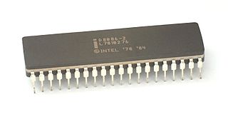
The 8086 is a 16-bit microprocessor chip designed by Intel between early 1976 and June 8, 1978, when it was released. The Intel 8088, released July 1, 1979, is a slightly modified chip with an external 8-bit data bus, and is notable as the processor used in the original IBM PC design.
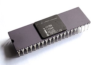
x86 is a family of complex instruction set computer (CISC) instruction set architectures initially developed by Intel based on the Intel 8086 microprocessor and its 8088 variant. The 8086 was introduced in 1978 as a fully 16-bit extension of Intel's 8-bit 8080 microprocessor, with memory segmentation as a solution for addressing more memory than can be covered by a plain 16-bit address. The term "x86" came into being because the names of several successors to Intel's 8086 processor end in "86", including the 80186, 80286, 80386 and 80486 processors. Colloquially, their names were "186", "286", "386" and "486".
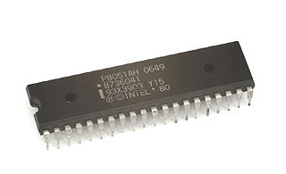
The Intel MCS-51 is a single chip microcontroller (MCU) series developed by Intel in 1980 for use in embedded systems. The architect of the Intel MCS-51 instruction set was John H. Wharton. Intel's original versions were popular in the 1980s and early 1990s, and enhanced binary compatible derivatives remain popular today. It is a complex instruction set computer, but also has some of the features of RISC architectures, such as a large register set and register windows, and has separate memory spaces for program instructions and data.
x86 memory segmentation refers to the implementation of memory segmentation in the Intel x86 computer instruction set architecture. Segmentation was introduced on the Intel 8086 in 1978 as a way to allow programs to address more than 64 KB (65,536 bytes) of memory. The Intel 80286 introduced a second version of segmentation in 1982 that added support for virtual memory and memory protection. At this point the original mode was renamed to real mode, and the new version was named protected mode. The x86-64 architecture, introduced in 2003, has largely dropped support for segmentation in 64-bit mode.
In computing, protected mode, also called protected virtual address mode, is an operational mode of x86-compatible central processing units (CPUs). It allows system software to use features such as segmentation, virtual memory, paging and safe multi-tasking designed to increase an operating system's control over application software.
x86-64 is a 64-bit version of the x86 instruction set, first announced in 1999. It introduced two new modes of operation, 64-bit mode and compatibility mode, along with a new 4-level paging mode.
An index register in a computer's CPU is a processor register used for pointing to operand addresses during the run of a program. It is useful for stepping through strings and arrays. It can also be used for holding loop iterations and counters. In some architectures it is used for read/writing blocks of memory. Depending on the architecture it may be a dedicated index register or a general-purpose register. Some instruction sets allow more than one index register to be used; in that case additional instruction fields may specify which index registers to use.
In computing, a memory address is a reference to a specific memory location used at various levels by software and hardware. Memory addresses are fixed-length sequences of digits conventionally displayed and manipulated as unsigned integers. Such numerical semantic bases itself upon features of CPU, as well upon use of the memory like an array endorsed by various programming languages.
The x86 instruction set refers to the set of instructions that x86-compatible microprocessors support. The instructions are usually part of an executable program, often stored as a computer file and executed on the processor.
Addressing modes are an aspect of the instruction set architecture in most central processing unit (CPU) designs. The various addressing modes that are defined in a given instruction set architecture define how the machine language instructions in that architecture identify the operand(s) of each instruction. An addressing mode specifies how to calculate the effective memory address of an operand by using information held in registers and/or constants contained within a machine instruction or elsewhere.
The TMS9900 was one of the first commercially available, single-chip 16-bit microprocessors. Introduced in June 1976, it implemented Texas Instruments' TI-990 minicomputer architecture in a single-chip format, and was initially used for low-end models of that lineup.
A register file is an array of processor registers in a central processing unit (CPU). The instruction set architecture of a CPU will almost always define a set of registers which are used to stage data between memory and the functional units on the chip. The register file is part of the architecture and visible to the programmer, as opposed to the concept of transparent caches. In simpler CPUs, these architectural registers correspond one-for-one to the entries in a physical register file (PRF) within the CPU. More complicated CPUs use register renaming, so that the mapping of which physical entry stores a particular architectural register changes dynamically during execution.
In computing, the x86 memory models are a set of six different memory models of the x86 CPU operating in real mode which control how the segment registers are used and the default size of pointers.
In the x86 architecture, the CPUID instruction is a processor supplementary instruction allowing software to discover details of the processor. It was introduced by Intel in 1993 with the launch of the Pentium and SL-enhanced 486 processors.
This article describes the calling conventions used when programming x86 architecture microprocessors.
The TI-990 was a series of 16-bit minicomputers sold by Texas Instruments (TI) in the 1970s and 1980s. The TI-990 was a replacement for TI's earlier minicomputer systems, the TI-960 and the TI-980. It had several unique features, and was easier to program than its predecessors.
C# Open Source Managed Operating System (Cosmos) is a toolkit for building GUI and command-line based operating systems, written mostly in the programming language C# and small amounts of a high-level assembly language named X#. Cosmos is a backronym, in that the acronym was chosen before the meaning. It is open-source software released under a BSD license.
The PDP-11 architecture is a 16-bit CISC instruction set architecture (ISA) developed by Digital Equipment Corporation (DEC). It is implemented by central processing units (CPUs) and microprocessors used in PDP-11 minicomputers. It was in wide use during the 1970s, but was eventually overshadowed by the more powerful VAX architecture in the 1980s.
The WD16 is a 16-bit microprocessor introduced by Western Digital in October 1976. It is based on the MCP-1600 chipset, a general-purpose design that was also used to implement the DEC LSI-11 low-end minicomputer and the Pascal MicroEngine processor. The three systems differed primarily in their microcode, giving each system a unique instruction set architecture (ISA).
This page is based on this Wikipedia article Text is available under the CC BY-SA 4.0 license; additional terms may apply. Images, videos and audio are available under their respective licenses.