
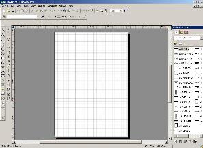
AutoCAD is a 2D and 3D computer-aided design (CAD) software application for desktop, web, and mobile developed by Autodesk. It was first released in December 1982 for the CP/M and IBM PC platforms as a desktop app running on microcomputers with internal graphics controllers. Initially a DOS application, subsequent versions were later released for other platforms including Classic Mac OS (1992), Microsoft Windows (1992), web browsers (2010), iOS (2010), macOS (2010), and Android (2011).

Computer-Aided Design (CAD) is the use of computers to aid in the creation, modification, analysis, or optimization of a design. This software is used to increase the productivity of the designer, improve the quality of design, improve communications through documentation, and to create a database for manufacturing. Designs made through CAD software help protect products and inventions when used in patent applications. CAD output is often in the form of electronic files for print, machining, or other manufacturing operations. The terms computer-aided drafting (CAD) and computer-aided design and drafting (CADD) are also used.

Caddie is a mid-range computer-assisted draughting (CAD) software package for 2D and 3D design. It is used primarily by architects, but has tools for surveyors and mechanical, civil and construction engineers. It was initially designed as an electronic drawing board, using concepts and tools clearly related to a physical board.
MicroStation is a CAD software platform for two- and three-dimensional design and drafting, developed and sold by Bentley Systems and used in the architectural and engineering industries. It generates 2D/3D vector graphics objects and elements and includes building information modeling (BIM) features. The current version is MicroStation CONNECT Edition.
DWG is a proprietary binary file format used for storing two- and three- dimensional design data and metadata. It is the native format for several CAD packages including DraftSight, AutoCAD, ZWCAD, IntelliCAD, Caddie and Open Design Alliance compliant applications. In addition, DWG is supported non-natively by many other CAD applications. The .bak, .dws, .dwt and .sv$ files are also DWG files.
CAD Standards are a set of guidelines for the way Computer-aided drafting (CAD), or (CADD) Computer Aided Design and Drawing, drawings should appear, to improve productivity and interchange of CAD documents between different offices and CAD programs, especially in architecture and engineering.
AutoSketch is a 2D vector drawing program by Autodesk. It is less powerful than Autodesk's AutoCAD and does not support 3D models.
Design Web Format (DWF) is a file format developed by Autodesk for the efficient distribution and communication of rich design data to anyone who needs to view, review, or print design files. Because DWF files are highly compressed, they are smaller and faster to transmit than design files, without the overhead associated with complex CAD drawings. With DWF functionality, publishers of design data can limit the specific design data and plot styles to only what they want recipients to see and can publish multisheet drawing sets from multiple AutoCAD drawings in a single DWF file. They can also publish 3D models from most Autodesk design applications.
Open Design Alliance is a nonprofit organization creating software development kits (SDKs) for engineering applications. ODA offers interoperability tools for CAD, BIM, and Mechanical industries including .dwg, .dxf, .dgn, Autodesk Revit, Autodesk Navisworks, and .ifc files and additional tools for visualization, web development, 3D PDF publishing and modeling.
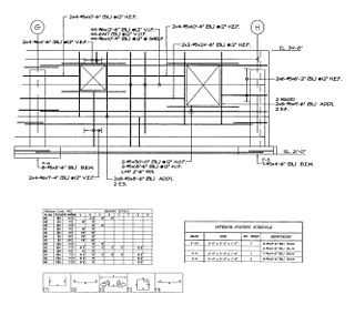
A shop drawing is a drawing or set of drawings produced by the contractor, supplier, manufacturer, subcontractor, consultants, or fabricator. Shop drawings are typically required for prefabricated components. Examples of these include: elevators, structural steel, trusses, pre-cast concrete, windows, appliances, cabinets, air handling units, and millwork. Also critical are the installation and coordination shop drawings of the MEP trades such as sheet metal ductwork, piping, plumbing, fire protection, and electrical. Shop drawings are produced by contractors and suppliers under their contract with the owner. The shop drawing is the manufacturer’s or the contractor’s drawn version of information shown in the construction documents. The shop drawing normally shows more detail than the construction documents. It is drawn to explain the fabrication and/or installation of the items to the manufacturer’s production crew or contractor's installation crews. The style of the shop drawing is usually very different from that of the architect’s drawing. The shop drawing’s primary emphasis is on the particular product or installation and excludes notation concerning other products and installations, unless integration with the subject product is necessary.

BricsCAD is a software application for computer-aided design (CAD), developed by Bricsys nv. The company was founded in 2002 by Erik de Keyser, a longtime CAD entrepreneur. In 2011 Bricsys acquired the intellectual property rights from Ledas for constraints-based parametric design tools, permitting the development of applications in the areas of direct modeling and assembly design. Bricsys is headquartered in Ghent, Belgium, and has additional development centers in Nizhny Novgorod and Novosibirsk, Russia; Bucharest, Romania and Singapore. Bricsys is a founding member of the Open Design Alliance, and joined the BuildingSMART International consortium in December 2016.
GRAITEC is an Autodesk reseller and developer of CAD / CAE software for the civil engineering and construction industries.
Advance Concrete is a computer-aided design (CAD) software application was developed by GRAITEC, but is now an Autodesk product, used for modeling and detailing reinforced concrete structures. Advance Concrete is used in the structural / civil engineering and drafting fields.
MPDS, the MEDUSA Plant Design System, is a suite of plant engineering applications for 2D/3D layout, design and modelling of process plants, factories or installations. The system's history is closely tied to the very beginnings of mainstream CAD and the research culture fostered by Cambridge University and the UK government as well as the resulting "Cambridge Phenomenon" MPDS was initially developed for 3D plant design and layout and piping design. Today, the software includes modules for 2D/3D factory layout, process and instrumentation diagrams (P&ID), mechanical handling systems design, steel design, ducting (HVAC) design, electrical design and hangers and supports Design. The latest version, MPDS4 5.2.1, was released for Microsoft Windows and Sun Solaris in February 2014.

Alibre Design is a 3D parametric computer aided design software suite developed by Alibre for Microsoft Windows. Available in fifteen languages. Alibre is a brand of Alibre, LLC, a company based in Texas.
FINE MEP is a BIM CAD software tool for Building services engineering design, built on top of IntelliCAD. It provides full IFC support, according to the 2x3 IFC Standard. FINE BIM structure, enables a smart model shaping and high design accuracy, directly applied to the real 3D-building model and its building services. Not only the building elements, but also the components of the mechanical/electrical installations themselves are all intelligent objects carrying their own attributes and interacting among each other. MEP design is supported by specific CAD commands and further facilitated through sophisticated recognition and validation algorithms, providing a user-friendly modeling environment.

SolveSpace is a free and open-source 2D/3D constraint-based parametric computer-aided design (CAD) software that supports basic 2D and 3D constructive solid geometry modeling.
The FORAN system is an integrated CAD/CAM/CAE system developed by SENER for the design and production of practically any naval ship and offshore unit. It is a multidisciplinary and integrated system that can be used in all the ship design and production phases and disciplines. The System collects all the information in a single database. FORAN is mainly focused on the design of:

C3D Toolkit is a proprietary cross-platform geometric modeling kit software developed by Russian by C3D Labs. It's written in C++. It can be licensed by other companies for use in their 3D computer graphics software products. The most widely known software in which C3D Toolkit is typically used are computer aided design (CAD), computer-aided manufacturing (CAM), and computer-aided engineering (CAE) systems.

ABViewer is multifunctional software for working with AutoCAD DWG, DXF, PLT, STEP, IGES, STL and other 2D and 3D CAD files. The application allows creating and editing drawings, as well as saving them to AutoCAD DWG/DXF, PDF, JPG and a number of other vector and raster file formats.

