Related Research Articles

Amplitude modulation (AM) is a modulation technique used in electronic communication, most commonly for transmitting messages with a radio wave. In amplitude modulation, the amplitude of the wave is varied in proportion to that of the message signal, such as an audio signal. This technique contrasts with angle modulation, in which either the frequency of the carrier wave is varied, as in frequency modulation, or its phase, as in phase modulation.
Frequency modulation (FM) is the encoding of information in a carrier wave by varying the instantaneous frequency of the wave. The technology is used in telecommunications, radio broadcasting, signal processing, and computing.
In electronics and telecommunications, modulation is the process of varying one or more properties of a periodic waveform, called the carrier signal, with a separate signal called the modulation signal that typically contains information to be transmitted. For example, the modulation signal might be an audio signal representing sound from a microphone, a video signal representing moving images from a video camera, or a digital signal representing a sequence of binary digits, a bitstream from a computer.
Phase modulation (PM) is a modulation pattern for conditioning communication signals for transmission. It encodes a message signal as variations in the instantaneous phase of a carrier wave. Phase modulation is one of the two principal forms of angle modulation, together with frequency modulation.
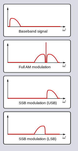
In radio communications, single-sideband modulation (SSB) or single-sideband suppressed-carrier modulation (SSB-SC) is a type of modulation used to transmit information, such as an audio signal, by radio waves. A refinement of amplitude modulation, it uses transmitter power and bandwidth more efficiently. Amplitude modulation produces an output signal the bandwidth of which is twice the maximum frequency of the original baseband signal. Single-sideband modulation avoids this bandwidth increase, and the power wasted on a carrier, at the cost of increased device complexity and more difficult tuning at the receiver.

A superheterodyne receiver, often shortened to superhet, is a type of radio receiver that uses frequency mixing to convert a received signal to a fixed intermediate frequency (IF) which can be more conveniently processed than the original carrier frequency. It was invented by French radio engineer and radio manufacturer Lucien Lévy. Virtually all modern radio receivers use the superheterodyne principle.

Frequency-shift keying (FSK) is a frequency modulation scheme in which digital information is encoded on a carrier signal by periodically shifting the frequency of the carrier between several discrete frequencies. The technology is used for communication systems such as telemetry, weather balloon radiosondes, caller ID, garage door openers, and low frequency radio transmission in the VLF and ELF bands. The simplest FSK is binary FSK, in which the carrier is shifted between two discrete frequencies to transmit binary information.
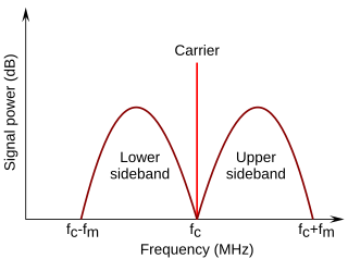
In radio communications, a sideband is a band of frequencies higher than or lower than the carrier frequency, that are the result of the modulation process. The sidebands carry the information transmitted by the radio signal. The sidebands comprise all the spectral components of the modulated signal except the carrier. The signal components above the carrier frequency constitute the upper sideband (USB), and those below the carrier frequency constitute the lower sideband (LSB). All forms of modulation produce sidebands.
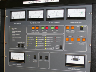
In electronics and telecommunications, a radio transmitter or just transmitter is an electronic device which produces radio waves with an antenna with the purpose of signal transmission up to a radio receiver. The transmitter itself generates a radio frequency alternating current, which is applied to the antenna. When excited by this alternating current, the antenna radiates radio waves.
Demodulation is extracting the original information-bearing signal from a carrier wave. A demodulator is an electronic circuit that is used to recover the information content from the modulated carrier wave. There are many types of modulation so there are many types of demodulators. The signal output from a demodulator may represent sound, images or binary data.

In telecommunications, frequency-division multiplexing (FDM) is a technique by which the total bandwidth available in a communication medium is divided into a series of non-overlapping frequency bands, each of which is used to carry a separate signal. This allows a single transmission medium such as a microwave radio link, cable or optical fiber to be shared by multiple independent signals. Another use is to carry separate serial bits or segments of a higher rate signal in parallel.

In telecommunications, a carrier wave, carrier signal, or just carrier, is a periodic waveform that carries no information that has one or more of its properties modified by an information-bearing signal for the purpose of conveying information.
Angle modulation is a class of carrier modulation that is used in telecommunications transmission systems. The class comprises frequency modulation (FM) and phase modulation (PM), and is based on altering the frequency or the phase, respectively, of a carrier signal to encode the message signal. This contrasts with varying the amplitude of the carrier, practiced in amplitude modulation (AM) transmission, the earliest of the major modulation methods used widely in early radio broadcasting.
The International Telecommunication Union uses an internationally agreed system for classifying radio frequency signals. Each type of radio emission is classified according to its bandwidth, method of modulation, nature of the modulating signal, and type of information transmitted on the carrier signal. It is based on characteristics of the signal, not on the transmitter used.
A television transmitter is a transmitter that is used for terrestrial (over-the-air) television broadcasting. It is an electronic device that radiates radio waves that carry a video signal representing moving images, along with a synchronized audio channel, which is received by television receivers belonging to a public audience, which display the image on a screen. A television transmitter, together with the broadcast studio which originates the content, is called a television station. Television transmitters must be licensed by governments, and are restricted to a certain frequency channel and power level. They transmit on frequency channels in the VHF and UHF bands. Since radio waves of these frequencies travel by line of sight, they are limited by the horizon to reception distances of 40–60 miles depending on the height of transmitter station.
Modulated continuous wave (MCW) is Morse code telegraphy transmitted using an audio tone to modulate a carrier wave.
A radio transmitter or just transmitter is an electronic device which produces radio waves with an antenna. Radio waves are electromagnetic waves with frequencies between about 30 Hz and 300 GHz. The transmitter itself generates a radio frequency alternating current, which is applied to the antenna. When excited by this alternating current, the antenna radiates radio waves. Transmitters are necessary parts of all systems that use radio: radio and television broadcasting, cell phones, wireless networks, radar, two way radios like walkie talkies, radio navigation systems like GPS, remote entry systems, among numerous other uses.

In radio, a detector is a device or circuit that extracts information from a modulated radio frequency current or voltage. The term dates from the first three decades of radio (1888–1918). Unlike modern radio stations which transmit sound on an uninterrupted carrier wave, early radio stations transmitted information by radiotelegraphy. The transmitter was switched on and off to produce long or short periods of radio waves, spelling out text messages in Morse code. Therefore, early radio receivers could reproduce the Morse code "dots" and "dashes" by simply distinguishing between the presence or absence of a radio signal. The device that performed this function in the receiver circuit was called a detector. A variety of different detector devices, such as the coherer, electrolytic detector, magnetic detector and the crystal detector, were used during the wireless telegraphy era until superseded by vacuum tube technology.
CCIR System A was the 405-line analog broadcast television system adopted in the UK and Ireland. System A service started in 1936 and was discontinued in 1985.