Related Research Articles

A mass driver or electromagnetic catapult is a proposed method of non-rocket spacelaunch which would use a linear motor to accelerate and catapult payloads up to high speeds. Existing and proposed mass drivers use coils of wire energized by electricity to make electromagnets, though a rotary mass driver has also been proposed. Sequential firing of a row of electromagnets accelerates the payload along a path. After leaving the path, the payload continues to move due to momentum.

A bullet is a kinetic projectile, a component of firearm ammunition that is shot from a gun barrel. They are made of a variety of materials, such as copper, lead, steel, polymer, rubber and even wax; and are made in various shapes and constructions, including specialized functions such as hunting, target shooting, training, and combat. Bullets are often tapered, making them more aerodynamic. Bullet size is expressed by weight and diameter in both imperial and metric measurement systems. Bullets do not normally contain explosives but strike or damage the intended target by transferring kinetic energy upon impact and penetration.

A projectile is an object that is propelled by the application of an external force and then moves freely under the influence of gravity and air resistance. Although any objects in motion through space are projectiles, they are commonly found in warfare and sports.

In guns, particularly firearms, but not artillery, where a different definition may apply, caliber is the specified nominal internal diameter of the gun barrel bore – regardless of how or where the bore is measured and whether the finished bore matches that specification. It is measured in inches or in millimeters. In the United States it is expressed in hundredths of an inch; in the United Kingdom in thousandths; and elsewhere in millimeters. For example, a US "45 caliber" firearm has a barrel diameter of roughly 0.45 inches (11.43mm). Barrel diameters can also be expressed using metric dimensions. For example, a "9 mm pistol" has a barrel diameter of about 9 millimeters. Since metric and US customary units do not convert evenly at this scale, metric conversions of caliber measured in decimal inches are typically approximations of the precise specifications in non-metric units, and vice versa.
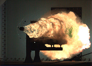
A railgun or rail gun, sometimes referred to as a rail cannon, is a linear motor device, typically designed as a weapon, that uses electromagnetic force to launch high-velocity projectiles. The projectile normally does not contain explosives, instead relying on the projectile's high kinetic energy to inflict damage. The railgun uses a pair of parallel conductors (rails), along which a sliding armature is accelerated by the electromagnetic effects of a current that flows down one rail, into the armature and then back along the other rail. It is based on principles similar to those of the homopolar motor.
A compensated pulsed alternator, also known by the portmanteau compulsator, is a form of power supply.
A coilgun is a type of mass driver consisting of one or more coils used as electromagnets in the configuration of a linear motor that accelerate a ferromagnetic or conducting projectile to high velocity. In almost all coilgun configurations, the coils and the gun barrel are arranged on a common axis. A coilgun is not a rifle as the barrel is smoothbore.
Muzzle velocity is the speed of a projectile with respect to the muzzle at the moment it leaves the end of a gun's barrel. Firearm muzzle velocities range from approximately 120 m/s (390 ft/s) to 370 m/s (1,200 ft/s) in black powder muskets, to more than 1,200 m/s (3,900 ft/s) in modern rifles with high-velocity cartridges such as the .220 Swift and .204 Ruger, all the way to 1,700 m/s (5,600 ft/s) for tank guns firing kinetic energy penetrator ammunition. To simulate orbital debris impacts on spacecraft, NASA launches projectiles through light-gas guns at speeds up to 8,500 m/s (28,000 ft/s). FPS and MPH are the most common American measurements for bullets. Several factors, including the type of firearm, the cartridge, and the barrel length, determine the bullet's muzzle velocity.
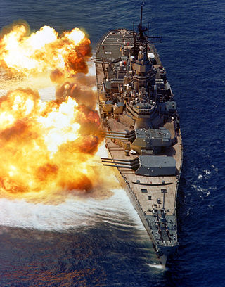
The 16"/50 caliber Mark 7 – United States Naval Gun is the main armament of the Iowa-class battleships and was the planned main armament of the cancelled Montana-class battleship.
A magnetic weapon is one that uses magnetic fields to accelerate or stop projectiles, or to focus charged particle beams. There are many hypothesized magnetic weapons, such as the railgun and coilgun which accelerate a magnetic mass to a high velocity, or ion cannons and plasma cannons which focus and direct charged particles using magnetic fields.
Magnetic gun may refer to:
The Springfield Model 1873 was the first standard-issue breech-loading rifle adopted by the United States Army. The rifle, in both full-length and carbine versions, was widely used in subsequent battles against Native Americans.
A proof test is a form of stress test to demonstrate the fitness of a load-bearing or impact-experiencing structure. An individual proof test may apply only to the unit tested, or to its design in general for mass-produced items. Such a structure is often subjected to loads above those expected in actual use, demonstrating safety and design margin. Proof testing is nominally a nondestructive test, particularly if both design margins and test levels are well-chosen. However, unit failures are by definition considered to have been destroyed for their originally-intended use and load levels.
Helical railguns are multi-turn railguns that reduce rail and brush current by a factor equal to the number of turns. Two rails are surrounded by a helical barrel and the projectile or re-usable carrier is cylindrical. The projectile is energized continuously by two brushes sliding along the rails, and two or more additional brushes on the projectile serve to energize and commute several windings of the helical barrel direction in front of and/or behind the projectile. The helical railgun is a cross between a railgun and a coilgun. They do not currently exist in a practical, usable form.
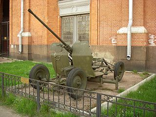
25 mm automatic air defense gun M1940 (72-K) was a Soviet 25 mm caliber anti-aircraft gun used during the World War II. The gun was developed from the end of 1939 to the beginning of 1940 at 8th Kalinin Artillery Plant under the guidance of its Chief Designer Mikhail Loginov, supervised by Lev Loktev. The cannon was given the factory code 72-K before being accepted into service by the Red Army as the 25 mm automatic air defense gun M1940.
The Electro-Magnetic Laboratory Rail Gun is a 32-megajoule electro-magnetic laboratory rail gun being evaluated by the US Office of Naval Research (ONR) Naval Air Warfare and Weapons Department. The US Navy is pursuing development of the launcher system through two industry teams – General Atomics and BAE Systems – to reduce risk in the program and to foster innovation in next-generation shipboard weapons. The same amount of energy is released by the detonation of 4.8 kg (11 lb) of C4.

In artillery, caliber or calibre is the internal diameter of a gun barrel, or, by extension, a relative measure of the barrel length.
A plasma railgun is a linear accelerator which, like a projectile railgun, uses two long parallel electrodes to accelerate a "sliding short" armature. However, in a plasma railgun, the armature and ejected projectile consists of plasma, or hot, ionized, gas-like particles, instead of a solid slug of material. Scientific plasma railguns are typically operated in vacuum and not at air pressure. They are of value because they produce muzzle velocities of up to several hundreds of kilometers per second. Because of this, these devices have applications in magnetic confinement fusion (MCF), magneto-inertial fusion (MIF), high energy density physics research (HEDP), laboratory astrophysics, and as a plasma propulsion engine for spacecraft.

The 10-pounder Parrott rifle, Model 1861 was a muzzle-loading rifled cannon made of cast iron that was adopted by the United States Army in 1861 and often used in field artillery units during the American Civil War. Like other Parrott rifles, the gun breech was reinforced by a distinctive band made of wrought iron. The 10-pounder Parrott rifle was capable of firing shell, shrapnel shell, canister shot, or solid shot. Midway through the war, the Federal government discontinued the 2.9 in (74 mm) version in favor of a 3.0 in (76 mm) version. Despite the reinforcing band, the guns occasionally burst without warning, which endangered the gun crews. The Confederate States of America manufactured a number of successful copies of the gun.

The 20-pounder Parrott rifle, Model 1861 was a cast iron muzzle-loading rifled cannon that was adopted by the United States Army in 1861 and employed in field artillery units during the American Civil War. As with other Parrott rifles, the gun breech was reinforced by a distinctive wrought iron reinforcing band. The gun fired a 20 lb (9.1 kg) projectile to a distance of 1,900 yd (1,737 m) at an elevation of 5°. The 20-pounder Parrott rifle could fire shell, shrapnel shell, canister shot, and more rarely solid shot. In spite of the reinforcing band, the 20-pounder earned a dubious reputation for bursting without warning, killing or injuring gunners. The Confederate States of America also manufactured copies of the gun.
References
- 1 2 3 4 5 6 7 8 9 10 11 12 13 Zielinski, Alexander; Werst, Michael (July 1995). Rapid Fire Railgun For The Cannon Caliber Electromagnetic Gun System. 8th Electromagnetic Launch Symposium. Baltimore, Maryland.
- ↑ Fontani, Harry (November 10, 1999). Electric Launch: An Inevitable Technology. 18th International Symposium on Ballistics. San Antonio, Texas. pp. 325–326. ISBN 9781566769013.
- ↑ Tzeng, Jerome; Schmidt, Edward (2004). "Advanced Materials Bring Electromagnetic Gun Technology One Step Closer to the Battlefield". AMPTIAC Quarterly. 8 (4): 79–84. CiteSeerX 10.1.1.383.9304 .
- 1 2 3 4 5 Werst, Michael; Hotz, Thomas; Kitzmiller, Jon; Penney, Chuck; Telander, R.M. (January 1997). "Testing of the Cannon Caliber Rapid Fire Railgun". IEEE Transactions on Magnetics. 33 (1): 613–618. Bibcode:1997ITM....33..613W. doi:10.1109/20.560084. hdl: 2152/30557 .
- 1 2 3 4 5 6 7 8 Zielinski, Alexander; Werst, Michael (January 1997). "Cannon-Caliber Electromagnetic Launcher". IEEE Transactions on Magnetics. 33 (1): 630–635. Bibcode:1997ITM....33..630Z. doi:10.1109/20.560087.
- 1 2 3 4 5 Zelinski, Alexander; Weinacht, Paul; Webb, David; Soencksen, Keith (March 1997). An Investigation of the Ballistic Performance for an Electromagnetic Gun-Launched Projectile (Report). The U.S. Army Research Laboratory. ADA326880. Archived from the original on April 25, 2022 – via Defense Technical Information Center.
- 1 2 Price, J.H.; Yun, H.D.; Kajs, J.P.; Kitzmiller, J.R.; Pratap, S.B.; Werst, M.D. (January 1995). "Discarding armature and barrel optimization for a cannon caliber electromagnetic launcher system". IEEE Transactions on Magnetics. 31 (1): 225–230. Bibcode:1995ITM....31..225P. doi:10.1109/20.364697. hdl: 2152/30918 .
- ↑ Zielinski, A.E.; Soencksen, K.; Webb, D.W.; Weinacht, P. (January 1997). "Integrated launch package performance in the cannon-caliber launcher". IEEE Transactions on Magnetics. 33 (1): 163–168. Bibcode:1997ITM....33..163Z. doi:10.1109/20.559936.
- ↑ Zielinski, A.; Hildenbrand, D. (January 1997). "Observation and simulation of armature contact performance in the cannon-caliber electromagnetic gun". IEEE Transactions on Magnetics. 33 (1): 157–162. Bibcode:1997ITM....33..157Z. doi:10.1109/20.559935.
- ↑ Zielinski, A.E.; Weinacht, P. (January 1999). "Effect of railgun electrodynamics on projectile launch dynamics". IEEE Transactions on Magnetics. 35 (1): 118–123. Bibcode:1999ITM....35..118Z. doi:10.1109/20.738388.
- ↑ Zielinski, A.E.; Weinacht, P.; Powell, J.D. (January 1999). "Effect of railgun electrodynamics on armature discard". IEEE Transactions on Magnetics. 35 (1): 112–117. Bibcode:1999ITM....35..112Z. doi:10.1109/20.738387.