Microwave is a form of electromagnetic radiation with wavelengths ranging from about one meter to one millimeter corresponding to frequencies between 300 MHz and 300 GHz respectively. Different sources define different frequency ranges as microwaves; the above broad definition includes both UHF and EHF bands. A more common definition in radio-frequency engineering is the range between 1 and 100 GHz. In all cases, microwaves include the entire SHF band at minimum. Frequencies in the microwave range are often referred to by their IEEE radar band designations: S, C, X, Ku, K, or Ka band, or by similar NATO or EU designations.

Radar is a radiolocation system that uses radio waves to determine the distance (ranging), angle (azimuth), and radial velocity of objects relative to the site. It is used to detect and track aircraft, ships, spacecraft, guided missiles, and motor vehicles, and map weather formations, and terrain. A radar system consists of a transmitter producing electromagnetic waves in the radio or microwaves domain, a transmitting antenna, a receiving antenna and a receiver and processor to determine properties of the objects. Radio waves from the transmitter reflect off the objects and return to the receiver, giving information about the objects' locations and speeds.

In telecommunications and radar, a Cassegrain antenna is a parabolic antenna in which the feed antenna is mounted at or behind the surface of the concave main parabolic reflector dish and is aimed at a smaller convex secondary reflector suspended in front of the primary reflector. The beam of radio waves from the feed illuminates the secondary reflector, which reflects it back to the main reflector dish, which reflects it forward again to form the desired beam. The Cassegrain design is widely used in parabolic antennas, particularly in large antennas such as those in satellite ground stations, radio telescopes, and communication satellites.

In antenna theory, a phased array usually means an electronically scanned array, a computer-controlled array of antennas which creates a beam of radio waves that can be electronically steered to point in different directions without moving the antennas.

In telecommunications and radar, a reflective array antenna is a class of directive antennas in which multiple driven elements are mounted in front of a flat surface designed to reflect the radio waves in a desired direction. They are a type of array antenna. They are often used in the VHF and UHF frequency bands. VHF examples are generally large and resemble a highway billboard, so they are sometimes called billboard antennas. Other names are bedspring array and bowtie array depending on the type of elements making up the antenna. The curtain array is a larger version used by shortwave radio broadcasting stations.

A parabolicreflector is a reflective surface used to collect or project energy such as light, sound, or radio waves. Its shape is part of a circular paraboloid, that is, the surface generated by a parabola revolving around its axis. The parabolic reflector transforms an incoming plane wave travelling along the axis into a spherical wave converging toward the focus. Conversely, a spherical wave generated by a point source placed in the focus is reflected into a plane wave propagating as a collimated beam along the axis.

A parabolic antenna is an antenna that uses a parabolic reflector, a curved surface with the cross-sectional shape of a parabola, to direct the radio waves. The most common form is shaped like a dish and is popularly called a dish antenna or parabolic dish. The main advantage of a parabolic antenna is that it has high directivity. It functions similarly to a searchlight or flashlight reflector to direct radio waves in a narrow beam, or receive radio waves from one particular direction only. Parabolic antennas have some of the highest gains, meaning that they can produce the narrowest beamwidths, of any antenna type. In order to achieve narrow beamwidths, the parabolic reflector must be much larger than the wavelength of the radio waves used, so parabolic antennas are used in the high frequency part of the radio spectrum, at UHF and microwave (SHF) frequencies, at which the wavelengths are small enough that conveniently-sized reflectors can be used.

A directional antenna or beam antenna is an antenna which radiates or receives greater radio wave power in specific directions. Directional antennas can radiate radio waves in beams, when greater concentration of radiation in a certain direction is desired, or in receiving antennas receive radio waves from one specific direction only. This can increase the power transmitted to receivers in that direction, or reduce interference from unwanted sources. This contrasts with omnidirectional antennas such as dipole antennas which radiate radio waves over a wide angle, or receive from a wide angle.
Super high frequency (SHF) is the ITU designation for radio frequencies (RF) in the range between 3 and 30 gigahertz (GHz). This band of frequencies is also known as the centimetre band or centimetre wave as the wavelengths range from one to ten centimetres. These frequencies fall within the microwave band, so radio waves with these frequencies are called microwaves. The small wavelength of microwaves allows them to be directed in narrow beams by aperture antennas such as parabolic dishes and horn antennas, so they are used for point-to-point communication and data links and for radar. This frequency range is used for most radar transmitters, wireless LANs, satellite communication, microwave radio relay links, satellite phones, and numerous short range terrestrial data links. They are also used for heating in industrial microwave heating, medical diathermy, microwave hyperthermy to treat cancer, and to cook food in microwave ovens.

A horn antenna or microwave horn is an antenna that consists of a flaring metal waveguide shaped like a horn to direct radio waves in a beam. Horns are widely used as antennas at UHF and microwave frequencies, above 300 MHz. They are used as feed antennas for larger antenna structures such as parabolic antennas, as standard calibration antennas to measure the gain of other antennas, and as directive antennas for such devices as radar guns, automatic door openers, and microwave radiometers. Their advantages are moderate directivity, broad bandwidth, low losses, and simple construction and adjustment.

A slot antenna consists of a metal surface, usually a flat plate, with one or more holes or slots cut out. When the plate is driven as an antenna by an applied radio frequency current, the slot radiates electromagnetic waves in a way similar to a dipole antenna. The shape and size of the slot, as well as the driving frequency, determine the radiation pattern. Slot antennas are usually used at UHF and microwave frequencies at which wavelengths are small enough that the plate and slot are conveniently small. At these frequencies, the radio waves are often conducted by a waveguide, and the antenna consists of slots in the waveguide; this is called a slotted waveguide antenna. Multiple slots act as a directive array antenna and can emit a narrow fan-shaped beam of microwaves. They are used in standard laboratory microwave sources used for research, UHF television transmitting antennas, antennas on missiles and aircraft, sector antennas for cellular base stations, and particularly marine radar antennas. A slot antenna's main advantages are its size, design simplicity, and convenient adaptation to mass production using either waveguide or PC board technology.

An antenna reflector is a device that reflects electromagnetic waves. Antenna reflectors can exist as a standalone device for redirecting radio frequency (RF) energy, or can be integrated as part of an antenna assembly.

An offset dish antenna or off-axis dish antenna is a type of parabolic antenna. It is so called because the antenna feed is offset to the side of the reflector, in contrast to the common "front-feed" parabolic antenna where the feed antenna is suspended in front of the dish, on its axis. As in a front-fed parabolic dish, the feed is located at the focal point of the reflector, but the reflector is an asymmetric segment of a paraboloid, so the focus is located to the side.
A fan-beam antenna is a directional antenna producing a main beam having a narrow beamwidth in one dimension and a wider beamwidth in the other dimension. This pattern will be achieved by a truncated paraboloid reflector or a circular paraboloid reflector. Since the reflector is narrow in the vertical plane and wide in the horizontal, it produces a beam that is wide in the vertical plane and narrow in the horizontal.

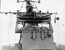
The AN/SPG-55 was an American tracking / illumination radar for Terrier and RIM-67 Standard missiles (SM-1ER/SM-2ER). It was used for target tracking and surface-to-air missile guidance as part of the Mk 76 missile fire control system. It was controlled by a UNIVAC 1218 computer.
An antenna array is a set of multiple connected antennas which work together as a single antenna, to transmit or receive radio waves. The individual antennas are usually connected to a single receiver or transmitter by feedlines that feed the power to the elements in a specific phase relationship. The radio waves radiated by each individual antenna combine and superpose, adding together to enhance the power radiated in desired directions, and cancelling to reduce the power radiated in other directions. Similarly, when used for receiving, the separate radio frequency currents from the individual antennas combine in the receiver with the correct phase relationship to enhance signals received from the desired directions and cancel signals from undesired directions. More sophisticated array antennas may have multiple transmitter or receiver modules, each connected to a separate antenna element or group of elements.

The Foster scanner, or Variable Path scanner, is a type of radar system that produces a narrow beam that rapidly scans an area in front of it. Foster scanners were widely used in post-World War II radar systems used for artillery and mortar spotting. Modern radars in this role normally use electronic scanning in place of a Foster scanner for this purpose.

The Type 271 was a surface search radar used by the Royal Navy and allies during World War II. The first widely used naval microwave-frequency system, it was equipped with an antenna small enough to allow it to be mounted on small ships like corvettes and frigates, while its improved resolution over earlier radars allowed it to pick up a surfaced U-boat at around 3 miles (4.8 km) and its periscope alone at 900 yards (820 m).

The Type 277 was a surface search and secondary aircraft early warning radar used by the Royal Navy and allies during World War II and the post-war era. It was a major update of the earlier Type 271 radar, offering much more power, better signal processing, new displays, and new antennas with greatly improved performance and much simpler mounting requirements. It allowed a radar with performance formerly found only on cruisers and battleships to be fitted even to the smallest corvettes. It began to replace the 271 in 1943 and was widespread by the end of the year.
In radio systems, many different antenna types are used whose properties are especially crafted for particular applications. Antennas can be classified in various ways. The list below groups together antennas under common operating principles, following the way antennas are classified in many engineering textbooks.