Cruciform wing

Last updated

A cruciform wing is a set of four individual wings arranged in the shape of a cross. The cross may take either of two forms; the wings may be equally spaced around the cross-section of the fuselage, lying in two planes at right angles, as on a typical missile, or they may lie together in a single horizontal plane about a vertical axis, as in the cruciform rotor wing or X-wing.

Contents

Cruciform-wing missile

A Canadair CL-89 shows its cruciform wing Cl-89 NATO AN USD-501.jpg
A Canadair CL-89 shows its cruciform wing

Rocket- and jet-propelled missiles often have a cruciform thin-wing arrangement in which four identical thin, low aspect ratio wings are equally spaced around a long, slender body. [1] Cruciform wing missiles are sometimes called Cruciform wing weapons (CWW) in contrast to planar wing weapons (PWW).

For wings of equal size and shape, this gives constant aerodynamic characteristics whatever the aircraft's angle of roll or direction of turn.

However, because only half the total lift of the four surfaces is available in any given attitude, the configuration is less efficient than a conventional planar wing.

The missile may also have small cruciform canard foreplane surfaces for flight trim and/or control. These may be set at 45° to the main wing, in order to minimise interference.

The aerodynamic properties of such a slender wing-plus-body configuration are different from those of the individual elements and the design needs to be evaluated as a unified form. A characteristic of the off-axis side forces is that they are relatively independent of the angle of pitch or yaw. [2]

Cruciform rotor wing

Sikorsky S-72 modified as the X-Wing testbed. It never flew. Sikorsky X-wing diagonal view.jpg
Sikorsky S-72 modified as the X-Wing testbed. It never flew.

The horizontal cruciform rotor wing, also known as the X-wing, is a form of the Stopped rotor. [3]

Teledyne Ryan studied the concept in the 1970s and took out a number of patents. [4] [5] The X-Wing circulation control rotor was developed in the mid-1970s under DARPA funding. The concept was first developed by the David W. Taylor Naval Ship Research and Development Center and an experimental rotor built by Lockheed Corporation, for testing on the Sikorsky S-72 Rotor Systems Research Aircraft (RSRA). [6] [7]

Intended to take off vertically like a helicopter, the rigid rotor could be stopped in mid-flight to act as an X-shape cruciform wing providing lift during forward flight, assisting the RSRA's conventional fixed wings. Instead of controlling lift by altering the angle of attack of its blades as more conventional helicopters do, the craft used compressed air fed from the engines and expelled from its blades to generate a virtual wing surface, similar to blown flaps on a conventional platform. Computerized valves made sure the compressed air came from the correct edge of the rotor, the correct edge changing as the rotor rotated. [8]

In late 1983 Sikorsky received a contract to modify the S-72 RSRA as a demonstration testbed for the X-Wing rotor and it was rolled out in 1986. The program was cancelled two years later, after the X-wing had been installed but before it had flown. [9] [10] [11]

Other proposed applications

Solar-powered aircraft

Around 1980 NASA was studying the technical aspects of long-duration solar-powered UAVs. One configuration studied was a very-high-aspect-ratio cruciform fixed wing with solar panels mounted along one plane of the wing. The craft was able to roll at any angle to follow the sun, thus maximising the power available without loss of lift. [12] [13]

Variable geometries

Bi-directional flying wing, plan view Wing bi-directional.svg
Bi-directional flying wing, plan view

Shortly after World War Two, the French company Matra began studies of a variable-geometry aircraft in which two sets of wings were provided, one for low-speed takeoff and landing, and the other for high-speed flight. Long-span wings for low speed flight were set at right angles to short-span wings for high-speed flight. One set lay horizontal for use as the lifting wings, while the other was set vertical. The supporting fuselage section could be rotated 90° to swap them over, and the unused set of wings could be folded backwards and partially or wholly retracted into the fuselage. It was patented by Matra's chief designer, Robert Roger, in 1946. [14]

The bi-directional wing is a similar approach to the same problem. It comprises a long-span low speed wing and a short-span high speed wing joined in the form of an unequal cross. The craft would take off and land with the low-speed wing across the airflow, then rotate it a quarter-turn so that the high-speed wing faces the airflow for supersonic travel. It has been studied in the form of a bi-directional flying wing. [15] [16]

Related Research Articles

<span class="mw-page-title-main">Aircraft</span> Vehicle or machine that is able to fly by gaining support from the air

An aircraft is a vehicle that is able to fly by gaining support from the air. It counters the force of gravity by using either static lift or the dynamic lift of an airfoil, or, in a few cases, direct downward thrust from its engines. Common examples of aircraft include airplanes, helicopters, airships, gliders, paramotors, and hot air balloons.

<span class="mw-page-title-main">VTOL</span> Aircraft takeoff and landing done vertically

A vertical take-off and landing (VTOL) aircraft is one that can take off and land vertically without relying on a runway. This classification can include a variety of types of aircraft including helicopters as well as thrust-vectoring fixed-wing aircraft and other hybrid aircraft with powered rotors such as cyclogyros/cyclocopters and gyrodynes.

<span class="mw-page-title-main">Fixed-wing aircraft</span> Heavier-than-air aircraft with fixed wings generating aerodynamic lift

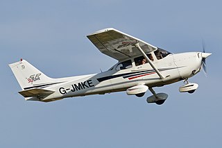
A fixed-wing aircraft is a heavier-than-air flying machine, such as an airplane, which is capable of flight using aerodynamic lift. Fixed-wing aircraft are distinct from rotary-wing aircraft, and ornithopters. The wings of a fixed-wing aircraft are not necessarily rigid; kites, hang gliders, variable-sweep wing aircraft, and airplanes that use wing morphing are all classified as fixed wing.

<span class="mw-page-title-main">Tiltrotor</span> Aircraft type

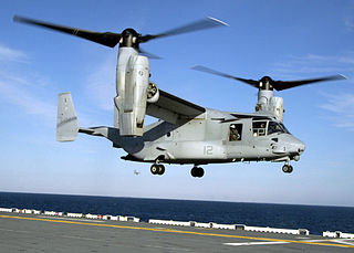
A tiltrotor is an aircraft that generates lift and propulsion by way of one or more powered rotors mounted on rotating shafts or nacelles usually at the ends of a fixed wing. Almost all tiltrotors use a transverse rotor design, with a few exceptions that use other multirotor layouts.

<span class="mw-page-title-main">Flying wing</span> Tailless fixed-wing aircraft that has no definite fuselage

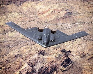
A flying wing is a tailless fixed-wing aircraft that has no definite fuselage, with its crew, payload, fuel, and equipment housed inside the main wing structure. A flying wing may have various small protuberances such as pods, nacelles, blisters, booms, or vertical stabilizers.

<span class="mw-page-title-main">Flight control surfaces</span> Surface that allows a pilot to adjust and control an aircrafts flight attitude

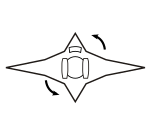
Aircraft flight control surfaces are aerodynamic devices allowing a pilot to adjust and control the aircraft's flight attitude.

<span class="mw-page-title-main">Thrust vectoring</span> Facet of ballistics and aeronautics

Thrust vectoring, also known as thrust vector control (TVC), is the ability of an aircraft, rocket or other vehicle to manipulate the direction of the thrust from its engine(s) or motor(s) to control the attitude or angular velocity of the vehicle.

Aircraft flight mechanics are relevant to fixed wing and rotary wing (helicopters) aircraft. An aeroplane, is defined in ICAO Document 9110 as, "a power-driven heavier than air aircraft, deriving its lift chiefly from aerodynamic reactions on surface which remain fixed under given conditions of flight".

<span class="mw-page-title-main">Vertical stabilizer</span> Aircraft component

A vertical stabilizer or tail fin is the static part of the vertical tail of an aircraft. The term is commonly applied to the assembly of both this fixed surface and one or more movable rudders hinged to it. Their role is to provide control, stability and trim in yaw. It is part of the aircraft empennage, specifically of its stabilizers.

<span class="mw-page-title-main">Boeing X-50 Dragonfly</span> US experimental drone aircraft

The Boeing X-50A Dragonfly, formerly known as the Canard Rotor/Wing Demonstrator, was a VTOL rotor wing experimental unmanned aerial vehicle that was developed by Boeing and DARPA to demonstrate the principle that a helicopter's rotor could be stopped in flight and act as a fixed wing, enabling it to transition between fixed-wing and rotary-wing flight.

<span class="mw-page-title-main">Stabilizer (aeronautics)</span> Aircraft component

An aircraft stabilizer is an aerodynamic surface, typically including one or more movable control surfaces, that provides longitudinal (pitch) and/or directional (yaw) stability and control. A stabilizer can feature a fixed or adjustable structure on which any movable control surfaces are hinged, or it can itself be a fully movable surface such as a stabilator. Depending on the context, "stabilizer" may sometimes describe only the front part of the overall surface.

<span class="mw-page-title-main">Oblique wing</span> Experimental aircraft wing design

An oblique wing is a variable geometry wing concept. On an aircraft so equipped, the wing is designed to rotate on center pivot, so that one tip is swept forward while the opposite tip is swept aft. By changing its sweep angle in this way, drag can be reduced at high speed without sacrificing low speed performance. This is a variation on the classic swing-wing design, intended to simplify construction and retain the center of gravity as the sweep angle is changed.

<span class="mw-page-title-main">Gyrodyne</span> Type of VTOL aircraft

A gyrodyne is a type of VTOL aircraft with a helicopter rotor-like system that is driven by its engine for takeoff and landing only, and includes one or more conventional propeller or jet engines to provide forward thrust during cruising flight. During forward flight the rotor is unpowered and free-spinning, like an autogyro, and lift is provided by a combination of the rotor and conventional wings. The gyrodyne is one of a number of similar concepts which attempt to combine helicopter-like low-speed performance with conventional fixed-wing high-speeds, including tiltrotors and tiltwings.

<span class="mw-page-title-main">Rotorcraft</span> Heavier-than-air aircraft which generates lift over rotating wings

A rotorcraft or rotary-wing aircraft is a heavier-than-air aircraft with rotary wings or rotor blades, which generate lift by rotating around a vertical mast. Several rotor blades mounted on a single mast are referred to as a rotor. The International Civil Aviation Organization (ICAO) defines a rotorcraft as "supported in flight by the reactions of the air on one or more rotors".

<span class="mw-page-title-main">Sikorsky S-72</span> US experimental compound helicopter (hybrid helicopter/fixed-wing aircraft)

The Sikorsky S-72 was an experimental Sikorsky Aircraft compound helicopter developed as the Rotor Systems Research Aircraft (RSRA) for the National Aeronautics and Space Administration (NASA) and the United States Army. The RSRA was a testbed for rotor and propulsion systems for high-speed.

<span class="mw-page-title-main">Tailless aircraft</span> Aircraft whose only horizontal aerodynamic surface is its main wing

In aeronautics, a tailless aircraft is an aircraft with no other horizontal aerodynamic surface besides its main wing. It may still have a fuselage, vertical tail fin, and/or vertical rudder.

<span class="mw-page-title-main">Wing configuration</span> Describes the general shape and layout of an aircraft wing

The wing configuration of a fixed-wing aircraft is its arrangement of lifting and related surfaces.

<span class="mw-page-title-main">VTOL X-Plane</span> American experimental aircraft

The Vertical Take-Off and Landing Experimental Aircraft program was an American research project sponsored by the Defense Advanced Research Projects Agency (DARPA). The goal of the program was to demonstrate a VTOL aircraft design that can take off vertically and efficiently hover, while flying faster than conventional rotorcraft. There have been many previous attempts, most of them unsuccessful as of 2015.

The period between 1945 and 1979 is sometimes called the post-war era or the period of the post-war political consensus. During this period, aviation was dominated by the arrival of the Jet Age. In civil aviation the jet engine allowed a huge expansion of commercial air travel, while in military aviation it led to the widespread introduction of supersonic aircraft.

References

Notes

  1. Farmer (1956)
  2. Spreiter (1950): "The lift and pitching moment are independent of the angle of yaw, and the side force and yawing moment are independent of the angle of attack. If the vertical and horizontal wings are identical, the rolling moment is zero for all angles of pitch and yaw. By symmetry considerations, these results are shown to be equally applicable for any cruciform-wing and body combination having identical horizontal and vertical wings of arbitrary plan form and aspect ratio."
  3. Eisenberg, Joseph D.; "The Selection of Convertible Engines With Current Gas Generator Technology for High Speed Rotorcraft", Technical Memorandum 103774, NASA, 1990, p.3 :"Figure 4 shows the X-wing concept. This aircraft uses its rotor for vertical lift and low speed cruise. The rotor is then stopped to form a cruciform wing, and auxiliary propulsion is applied," and, "Figure 4. X-Wing Stopped-Rotor Aircraft".
  4. Girard, Peter F. (Teledyne Ryan); "VTOL aircraft with cruciform rotor wing", US Patent 3792827, filed 1972, issued 1974.
  5. Girard, Peter F. (Teledyne Ryan); "Aircraft with retractable rotor wing", US Patent 3986686: "Cruciform rotor wing", filed 1975, issued 1976.
  6. Warwick, Graham (August 9, 2008). "X-Wing". DARPA 50th Anniversary Gallery. Aviation Week & Space Technology . Retrieved October 26, 2012.
  7. Carlisle, Rodney P. (1998). Where the Fleet Begins: A History of the David Taylor Research Center, 1898–1998. Department of the Navy. pp. 373–9. ISBN   0-160494-427.
  8. Reader, Kenneth R; Wilkerson, Joseph B (2008) [1976]. Circulation Control Applied to a High Speed Helicopter Rotor (PDF). David W. Taylor Naval Ship Research and Development Center. Archived (PDF) from the original on March 3, 2017.
  9. "X-Wing scheduled to fly in October" (PDF). Flight International: 18. 22 February 1986.
  10. "Darpa ditches X-Wing" (PDF). Flight International: 2. 16 January 1988.
  11. Art Linden, Ken Rosen and Andy White; "X-Wing", Sikorsky Product History, 2013. (retrieved 5 August 2018)
  12. Phillips, W. H.; "Solar-powered aircraft"; Document Type: NASA Technical Brief LAR-12615, 1981.
  13. Phillips, W. H.; "Solar-powered aircraft"; US patent 4,415,133, Filed 1981, Issued 1983.
  14. Robert, Roger Aimeé; "Improvements in or Relating to Aircraft", UK Patent 11006/47, accepted 1949.
  15. Zha, Im & Espinal, Toward Zero Sonic-Boom and High Efficiency Supersonic Flight: A Novel Concept of Supersonic Bi-Directional Flying Wing
  16. NIAC 2012 Phase I & Phase II Awards Announcement

Bibliography