The driver ADP3418 chip (bottom left), used for driving high-power field transistors in voltage converters. Above it is seen next to such a transistor (06N03LA), probably driven by that driver.
They are usually used to regulate current flowing through a circuit or to control other factors such as other components and some other devices in the circuit. The term is often used, for example, for a specialized integrated circuit that controls high-power switches in switched-mode power converters. An amplifier can also be considered a driver for loudspeakers, or a voltage regulator that keeps an attached component operating within a broad range of input voltages.
Typically the driver stage(s) of a circuit requires different characteristics to other circuit stages. For example, in a transistor power amplifier circuit, typically the driver circuit requires current gain, often the ability to discharge the following transistor bases rapidly, and low output impedance to avoid or minimize distortion.
An amplifier, electronic amplifier or (informally) amp is an electronic device that can increase the power of a signal. It is a two-port electronic circuit that uses electric power from a power supply to increase the amplitude of a signal applied to its input terminals, producing a proportionally greater amplitude signal at its output. The amount of amplification provided by an amplifier is measured by its gain: the ratio of output voltage, current, or power to input. An amplifier is a circuit that has a power gain greater than one.
An operational amplifier is a DC-coupled high-gain electronic voltage amplifier with a differential input and, usually, a single-ended output. In this configuration, an op amp produces an output potential that is typically 100,000 times larger than the potential difference between its input terminals. Operational amplifiers had their origins in analog computers, where they were used to perform mathematical operations in linear, non-linear, and frequency-dependent circuits.
A transistor is a semiconductor device used to amplify or switch electrical signals and power. The transistor is one of the basic building blocks of modern electronics. It is composed of semiconductor material, usually with at least three terminals for connection to an electronic circuit. A voltage or current applied to one pair of the transistor's terminals controls the current through another pair of terminals. Because the controlled (output) power can be higher than the controlling (input) power, a transistor can amplify a signal. Some transistors are packaged individually, but many more are found embedded in integrated circuits.
Transistor–transistor logic (TTL) is a logic family built from bipolar junction transistors. Its name signifies that transistors perform both the logic function and the amplifying function, as opposed to resistor–transistor logic (RTL) or diode–transistor logic (DTL).
In electronics, a multi-transistor configuration called the Darlington configuration is a circuit consisting of two bipolar transistors with the emitter of one transistor connected to the base of the other, such that the current amplified by the first transistor is amplified further by the second one. The collectors of both transistors are connected together. This configuration has a much higher current gain than each transistor taken separately. It acts like and is often packaged as a single transistor. It was invented in 1953 by Sidney Darlington.
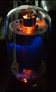
A valve amplifier or tube amplifier is a type of electronic amplifier that uses vacuum tubes to increase the amplitude or power of a signal. Low to medium power valve amplifiers for frequencies below the microwaves were largely replaced by solid state amplifiers in the 1960s and 1970s. Valve amplifiers can be used for applications such as guitar amplifiers, satellite transponders such as DirecTV and GPS, high quality stereo amplifiers, military applications and very high power radio and UHF television transmitters.
In electronics, a sample and hold circuit is an analog device that samples the voltage of a continuously varying analog signal and holds its value at a constant level for a specified minimum period of time. Sample and hold circuits and related peak detectors are the elementary analog memory devices. They are typically used in analog-to-digital converters to eliminate variations in input signal that can corrupt the conversion process. They are also used in electronic music, for instance to impart a random quality to successively-played notes.
A DC-to-DC converter is an electronic circuit or electromechanical device that converts a source of direct current (DC) from one voltage level to another. It is a type of electric power converter. Power levels range from very low to very high.
A voltage regulator is a system designed to automatically maintain a constant voltage. A voltage regulator may use a simple feed-forward design or may include negative feedback. It may use an electromechanical mechanism, or electronic components. Depending on the design, it may be used to regulate one or more AC or DC voltages.
A push–pull amplifier is a type of electronic circuit that uses a pair of active devices that alternately supply current to, or absorb current from, a connected load. This kind of amplifier can enhance both the load capacity and switching speed.
An electronic component is any basic discrete device or physical entity in an electronic system used to affect electrons or their associated fields. Electronic components are mostly industrial products, available in a singular form and are not to be confused with electrical elements, which are conceptual abstractions representing idealized electronic components and elements.
A class-D amplifier or switching amplifier is an electronic amplifier in which the amplifying devices operate as electronic switches, and not as linear gain devices as in other amplifiers. They operate by rapidly switching back and forth between the supply rails, being fed by a modulator using pulse width, pulse density, or related techniques to encode the audio input into a pulse train. The audio passes through a simple low-pass filter into the loudspeaker. The high-frequency pulses are blocked. Since the pairs of output transistors are never conducting at the same time, there is no other path for current flow apart from the low-pass filter/loudspeaker. For this reason, efficiency can exceed 90%.
A radio transmitter or just transmitter is an electronic device which produces radio waves with an antenna. Radio waves are electromagnetic waves with frequencies between about 30 Hz and 300 GHz. The transmitter itself generates a radio frequency alternating current, which is applied to the antenna. When excited by this alternating current, the antenna radiates radio waves. Transmitters are necessary parts of all systems that use radio: radio and television broadcasting, cell phones, wireless networks, radar, two way radios like walkie talkies, radio navigation systems like GPS, remote entry systems, among numerous other uses.
A H-bridge is an electronic circuit that switches the polarity of a voltage applied to a load. These circuits are often used in robotics and other applications to allow DC motors to run forwards or backwards. The name is derived from its common schematic diagram representation, with four switching elements configured as the branches of a letter "H" and the load connected as the cross-bar.
In electronics, biasing is the setting of DC operating conditions of an active device in an amplifier. Many electronic devices, such as diodes, transistors and vacuum tubes, whose function is processing time-varying (AC) signals, also require a steady (DC) current or voltage at their terminals to operate correctly. This current or voltage is called bias. The AC signal applied to them is superposed on this DC bias current or voltage.
Emission-aware programming is a design philosophy aiming to reduce the amount of electromagnetic radiation emitted by electronic devices through proper design of the software executed by the device, rather than changing the hardware.
A valve RF amplifier or tube amplifier (U.S.) is a device for electrically amplifying the power of an electrical radio frequency signal.
Tube sound is the characteristic sound associated with a vacuum tube amplifier, a vacuum tube-based audio amplifier. At first, the concept of tube sound did not exist, because practically all electronic amplification of audio signals was done with vacuum tubes and other comparable methods were not known or used. After introduction of solid state amplifiers, tube sound appeared as the logical complement of transistor sound, which had some negative connotations due to crossover distortion in early transistor amplifiers. However, solid state amplifiers have been developed to be flawless and the sound is later regarded neutral compared to tube amplifiers. Thus the tube sound now means 'euphonic distortion.' The audible significance of tube amplification on audio signals is a subject of continuing debate among audio enthusiasts.
A gate driver is a power amplifier that accepts a low-power input from a controller IC and produces a high-current drive input for the gate of a high-power transistor such as an IGBT or power MOSFET. Gate drivers can be provided either on-chip or as a discrete module. In essence, a gate driver consists of a level shifter in combination with an amplifier. A gate driver IC serves as the interface between control signals and power switches. An integrated gate-driver solution reduces design complexity, development time, bill of materials (BOM), and board space while improving reliability over discretely-implemented gate-drive solutions.
In electronics, power amplifier classes are letter symbols applied to different power amplifier types. The class gives a broad indication of an amplifier's characteristics and performance. The classes are related to the time period that the active amplifier device is passing current, expressed as a fraction of the period of a signal waveform applied to the input. A class A amplifier is conducting through all the period of the signal; Class B only for one-half the input period, class C for much less than half the input period. A Class D amplifier operates its output device in a switching manner; the fraction of the time that the device is conducting is adjusted so a pulse-width modulation output is obtained from the stage.
This page is based on this Wikipedia article Text is available under the CC BY-SA 4.0 license; additional terms may apply. Images, videos and audio are available under their respective licenses.