A vertically polarized blade antenna on a military aircraft in Japan. This is not a dual-band type.
A dual-band blade antenna is a type of blade antenna that is mounted on the fuselage of an aircraft and provides in flight direction a narrow width and minimal height, in the form of a blade. With increasing speed of aircraft the drag increases, therefore to minimize the aerodynamicfairing, to reduce low air drag and to reduce corrosion compared to wire- or tube-type aircraft antennas, the antennas were placed in a blade shaped radome. Blade antenna are used for avionics systems supporting the aeronauticalmobile (route) service (AM(R)S, VHF- and UHF-voice-communication and -Data-Link) and aeronautical radio navigation systems (ARNS, DME, TACAN, IFF, SSR, ILS-LLZ, ILS-GP, VOR, GBAS). The designation blade-antenna was adopted first by ARINC in 1962 for the blade like radome shape protecting the antenna in ARINC Characteristic 521C for Airborne Distance Measuring Equipment (DME).[1]
Dual-band blade-antennas are designed to support reception and/or transmission for two or more aeronautical frequency bands, e.g. for small aircraft or when the existing space of the fuselage of an aircraft does not allow placement of additional antennas.
Dual-Band Blade antennas are available for both vertical (VHF- and UHF-COM, DME, TACAN, IFF and SSR) and horizontally polarised aeronautical systems (ILS-LLZ, ILS-GP, VOR, GBAS). While most blade antennas provide more or less omnidirectional and directional antenna diagrams due to other fixed or moveable protruding objects on the fuselage of an aircraft, they can also provide directional coverage when needed, e.g. for ILS-LLZ and -GP use or 4 separate sectors for ACAS (TCAS). Omnidirectional vertically polarized dual-band blade-antennas are available e.g. for use as VHF- and UHF-communication antenna type S65-8262-305, or use as UHF-Communication and for aeronautical systems in the L-Band like DME, TACAN, IFF and SSR, e.g. CNI8 Type UHF- und L-Band antennas[2] and consist of a 1/4 λ monopoles. Horizontally polarized dual-band blade-antennas are designed for the reception of the horizontally polarized aeronautical VHF navigation systems ILS-LLZ, VOR and GBAS and provide additional support for UHF-Band reception of ILS-GP signals, e.g. S65-247-17[3] and use loop type antennas.
Multiband blade-antennas for Emergency location transmitter (ELT) for emergency location service can support transmission on three freqencies 406MHz, 121.5MHz and 243.0MHz, e.g. type S65-1231[4]
Introduction
A typical monopole antenna radiates radio power equally in all azimuth directions perpendicular to its axis, with signal strength decreasing as the elevation angle increases until it reaches zero at the zenith.
When there is a ground plane under a monopole, the monopole antenna can be thought of as a dipole antenna where one end of it becomes the ground plane for the monopole device. By this line of conceptual thinking, one can easily conclude that the radiation emanating from a monopole antenna exists in half the space of a similar dipole antenna. Therefore, the maximum gain is twice that of a typical dipole, or an additional 3dB. Hence, the nominal value of maximum gain for a monopole antenna is about 5.15dBi.
Stutzman puts it succinctly as follows:
...A monopole is a dipole that has been divided in half at its center feed point and fed against a ground plane...[5]
This article covers one type of dual-band blade monopole. This is the slot inside a monopole. Computational Electromagnetic Modeling (CEM) is used to provide graphics of operations for a more conceptual understanding.
Dual-band works in dual mode. It operates on the basis of Ohm's law V=IR, where V=voltage, I=current, and R=resistance.
Theory
Monopoles
Monopole equations can be derived by inspection of dipole antenna derivations, with the understanding that all radiation occurs in half the volume above the ground plane when compared to the dipole antenna. This leads to the following equations:
As can be seen in the "Relationship of monopoles and dipoles" section of the linked radiation resistance article.
Blade Antennas
A blade antenna is an attempt to create a broader-band monopole when compared to a thin wire monopole. Most blade antennas are trapezoidal in shape. Variations have been made on this shape for aerodynamic purposes, and notches have been introduced in order to achieve a better broadband performance. This type of monopole antenna is generally used in aviation for VHF and UHF frequency ranges.
For more information, see the Antenna Engineering Handbook.[6]
Slot Antennas
A slot antenna can be viewed as a dipole with an opposite polarization. This is due to the typical feed, which sets the orientation of the electric field (E-field) across the smallest linear dimension of the slot. The following equations can be used to 'translate' a vertical or horizontal slot antenna into its complement (dipole):
where the subscript S denotes the opening on the screen and the subscript C denotes its complement (a dipole). Additionally, , where is the complex permeability and is the complex permittivity of the medium into which one is radiating. This assumes an unbounded medium. In addition, all slot equations assume a screen thickness much less than a wavelength (, where λ is the signal wavelength). If these were not held to be true, fringing and the existence of modes could not be ignored.
This is defined by Babinet's principle, and Booker's Extension further expands this principle to include polarization. The simple equations from Babinet's principle are stated on the linked page, to which the author has contributed.
Dual Band Antennas
Dual-band antennas are not a new idea. For years, many manufactures have combined multiple elements to create antennas that operate in two separate bands (not to be confused with so-called frequency-independent antennas, such as a log-periodic antenna).
One method to create a dual-band blade antenna is to create a slot in a blade antenna that is less than or on the order of , ensuring that the lower frequency does not 'see' the slot (it is a rule of thumb that the perturbation created by a discontinuity less than on a structure is negligible).
Computational Electromagnetic Modeling (CEM)
Computational Electromagnetic Modeling (CEM) uses various methods to numerically calculate an antenna pattern.
To the untrained eye, this may seem a trivial. Although, with some research and thought, one will realize that all local structures affect the radiation pattern whether by reflection, absorption, refraction, fringing, or as part of the radiating structure. Some structure that are not local will also cause these items and more including blockage and 're-radiation'. With this in mind, the calculation can become cumbersome.
Multiple algorithms exist in CEM, including but not limited to the Method of Moments (MoM), Finite Element Method (FEM), and Uniform Theory of Diffraction (UTD). Two examples of software packages that use these methods in free-space are FEKO and WIPL-D. The examples shown here are from WIPL-D. It is important to note that these software packages must be used by someone who understands the process and can determine whether the calculated results are accurate or if errors in the model and input data have let to false output data (adhering to the old adage that 'garbage in equals garbage out').
Dual Band Blade Antenna Example
This example will use a design for an approximately frequency for 460MHz Telemetry and GPS frequency L1 (1575.42MHz) in a single package (I hesitate to call it a single antenna because there are two radiating elements, each requiring its own balun for matching). Please note that these are not match to any transmission line, so the design will not be practical for use; it is solely for demonstration purposes.
Below, you will see the simulation setup used for the simulations. The ground plane is twice the wavelength at 460MHz.
Model used for Simulation
Below is a comparison of the horizontal radiation patterns at L1 for both the blade and the slot. The slot exhibits a figure-8 dipole pattern with decent gain, whereas the blade still radiates, but with lower gain and a very lob-like pattern creating nulls. Please note, for a larger image, follow the link in each caption or simply click on the image (clicking on the image will provide better quality).
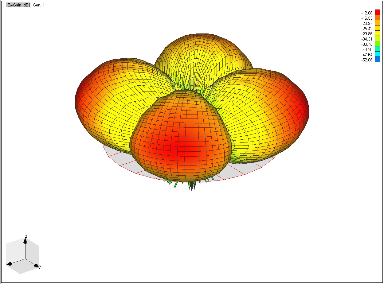
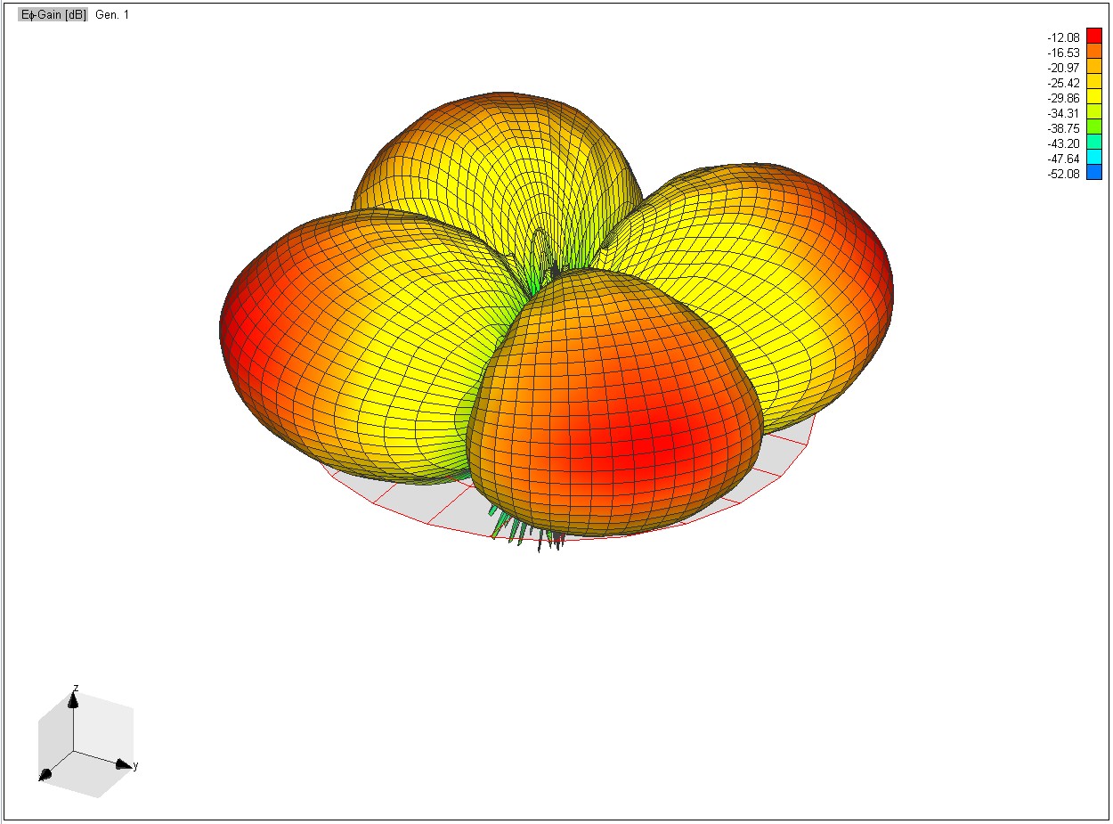
L1 Horizontal Radiation Patterns
Horizontal Polarization Radiation Pattern for the Slot at L1 Link.
Horizontal Polarization Radiation Pattern for the Blade at L1 Link.
One will also note the polarization of the two elements. As stated before, the polarization of the slot is due to its feed, which is generally across the smallest linear dimension. Hence, this slot is horizontally polarized with respect to the ground plane, and the blade is vertically polarized with respect to the ground plane.
L1 Vertical Radiation Patterns
Vertical Polarization Radiation Pattern for the Slot at L1 Link.
Vertical Polarization Radiation Pattern for the Blade at L1 Link.
Here we are seeing the vertically polarized radiation patterns or Vpol for 460MHz.
460MHz Vertical Radiation Patterns
Vertical Polarization Radiation Pattern for the Slot at 460MHz Link.
Vertical Polarization Radiation Pattern for the Blade at 460MHz Link.
Whereas presented here we can see the Hpol radiation pattern for both the blade and slot elements.
460MHz Horizontal Radiation Patterns
Horizontal Polarization Radiation Pattern for the Slot at 460MHz Link.
Horizontal Polarization Radiation Pattern for the Blade at 460MHz Link.
Conclusion
By the preceding section, it is seen that a dual band blade antenna can be both polarity diverse and dual-band. The bands chosen for this example are relatively close in frequency and to provide a limited demonstration of the capabilities of such a device, yet they illustrate what can be achieved. With sufficient space, one can cover two very different bands effectively, each with opposite polarization.
It also clearly illustrates that the impact of the rectangular slot radiating element non the radiation pattern of the lower frequency monopole is negligible. This is due to the previously mentioned rule of thumb, which advises keeping the slot smaller than one-tenth the frequency of operation of the blade, ensuring that the lower frequency does not 'see' the slot.
By combining two elements in this manner, one reduces costs in manufacturing and saves space in mounting the antenna. It is noteworthy to mention again that each radiating element must have a different feed structure and likely a different matching network.
1234Stutzman, Warren L., and Gary A. Theiele. Antenna Theory and Design. 2nd Ed. New York: 1998. ISBN0-471-02590-9
↑Antenna Engineering Handbook. Ed. Richard C. Johnson. Ed. Henry Jasik. 3rd ed. New York: McGraw-Hill 1993. ISBN0-07-032381-X
↑Balanis, Constantine A. Antenna Theory, Analysis and Design. 3rd Ed. New Jersey: John Wiley & Sons, INC., 2005. ISBN0-471-66782-X
This page is based on this Wikipedia article Text is available under the CC BY-SA 4.0 license; additional terms may apply. Images, videos and audio are available under their respective licenses.


