Related Research Articles

An electronic oscillator is an electronic circuit that produces a periodic, oscillating electronic signal, often a sine wave or a square wave or a triangle wave. Oscillators convert direct current (DC) from a power supply to an alternating current (AC) signal. They are widely used in many electronic devices ranging from simplest clock generators to digital instruments and complex computers and peripherals etc. Common examples of signals generated by oscillators include signals broadcast by radio and television transmitters, clock signals that regulate computers and quartz clocks, and the sounds produced by electronic beepers and video games.

An amplifier, electronic amplifier or (informally) amp is an electronic device that can increase the power of a signal. It is a two-port electronic circuit that uses electric power from a power supply to increase the amplitude of a signal applied to its input terminals, producing a proportionally greater amplitude signal at its output. The amount of amplification provided by an amplifier is measured by its gain: the ratio of output voltage, current, or power to input. An amplifier is a circuit that has a power gain greater than one.

An operational amplifier is a DC-coupled high-gain electronic voltage amplifier with a differential input and, usually, a single-ended output. In this configuration, an op amp produces an output potential that is typically 100,000 times larger than the potential difference between its input terminals. Operational amplifiers had their origins in analog computers, where they were used to perform mathematical operations in linear, non-linear, and frequency-dependent circuits.
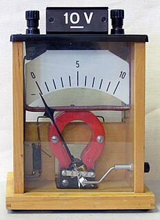
A voltmeter is an instrument used for measuring electric potential difference between two points in an electric circuit. It is connected in parallel. It usually has a high resistance so that it takes negligible current from the circuit.

A multimeter is a measuring instrument that can measure multiple electrical properties. A typical multimeter can measure voltage, resistance, and current, in which case it is also known as a volt-ohm-milliammeter (VOM), as the unit is equipped with voltmeter, ammeter, and ohmmeter functionality. Some feature the measurement of additional properties such as temperature and capacitance.

In electronics and control system theory, loop gain is the sum of the gain, expressed as a ratio or in decibels, around a feedback loop. Feedback loops are widely used in electronics in amplifiers and oscillators, and more generally in both electronic and nonelectronic industrial control systems to control industrial plant and equipment. The concept is also used in biology. In a feedback loop, the output of a device, process or plant is sampled and applied to alter the input, to better control the output. The loop gain, along with the related concept of loop phase shift, determines the behavior of the device, and particularly whether the output is stable, or unstable, which can result in oscillation. The importance of loop gain as a parameter for characterizing electronic feedback amplifiers was first recognized by Heinrich Barkhausen in 1921, and was developed further by Hendrik Wade Bode and Harry Nyquist at Bell Labs in the 1930s.
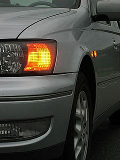
In electronics a relaxation oscillator is a nonlinear electronic oscillator circuit that produces a nonsinusoidal repetitive output signal, such as a triangle wave or square wave. The circuit consists of a feedback loop containing a switching device such as a transistor, comparator, relay, op amp, or a negative resistance device like a tunnel diode, that repetitively charges a capacitor or inductor through a resistance until it reaches a threshold level, then discharges it again. The period of the oscillator depends on the time constant of the capacitor or inductor circuit. The active device switches abruptly between charging and discharging modes, and thus produces a discontinuously changing repetitive waveform. This contrasts with the other type of electronic oscillator, the harmonic or linear oscillator, which uses an amplifier with feedback to excite resonant oscillations in a resonator, producing a sine wave. Relaxation oscillators are used to produce low frequency signals for applications such as blinking lights and electronic beepers and in voltage controlled oscillators (VCOs), inverters and switching power supplies, dual-slope analog to digital converters, and function generators.

In electronics, negative resistance (NR) is a property of some electrical circuits and devices in which an increase in voltage across the device's terminals results in a decrease in electric current through it.
The Hartley oscillator is an electronic oscillator circuit in which the oscillation frequency is determined by a tuned circuit consisting of capacitors and inductors, that is, an LC oscillator. The circuit was invented in 1915 by American engineer Ralph Hartley. The distinguishing feature of the Hartley oscillator is that the tuned circuit consists of a single capacitor in parallel with two inductors in series, and the feedback signal needed for oscillation is taken from the center connection of the two inductors.

A voltage-controlled oscillator (VCO) is an electronic oscillator whose oscillation frequency is controlled by a voltage input. The applied input voltage determines the instantaneous oscillation frequency. Consequently, a VCO can be used for frequency modulation (FM) or phase modulation (PM) by applying a modulating signal to the control input. A VCO is also an integral part of a phase-locked loop. VCOs are used in synthesizers to generate a waveform whose pitch can be adjusted by a voltage determined by a musical keyboard or other input.

A voltage regulator is a system designed to automatically maintain a constant voltage. A voltage regulator may use a simple feed-forward design or may include negative feedback. It may use an electromechanical mechanism, or electronic components. Depending on the design, it may be used to regulate one or more AC or DC voltages.
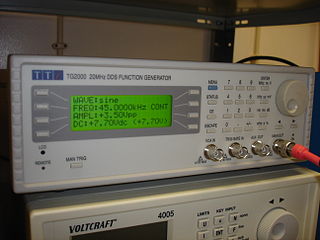
A function generator is usually a piece of electronic test equipment or software used to generate different types of electrical waveforms over a wide range of frequencies. Some of the most common waveforms produced by the function generator are the sine wave, square wave, triangular wave and sawtooth shapes. These waveforms can be either repetitive or single-shot. Integrated circuits used to generate waveforms may also be described as function generator ICs.

A ring oscillator is a device composed of an odd number of NOT gates in a ring, whose output oscillates between two voltage levels, representing true and false. The NOT gates, or inverters, are attached in a chain and the output of the last inverter is fed back into the first.

A pentode is an electronic device having five active electrodes. The term most commonly applies to a three-grid amplifying vacuum tube, which was invented by Gilles Holst and Bernhard D.H. Tellegen in 1926. The pentode consists of an evacuated glass envelope containing five electrodes in this order: a filament for indirectly heating a cathode, a control grid, a screen grid, a suppressor grid, and a plate (anode). The pentode was developed from the tetrode tube by the addition of a third grid, the suppressor grid. This served to prevent secondary emission electrons emitted by the plate from reaching the screen grid, which caused instability and parasitic oscillations in the tetrode. The pentode is closely related to the beam tetrode. Pentodes were widely used in industrial and consumer electronic equipment such as radios and televisions until the 1960s, when they were replaced by transistors. Their main use now is in high power industrial applications such as radio transmitters. The obsolete consumer tubes are still used in a few legacy and specialty vacuum tube audio devices.

Clipping is a form of waveform distortion that occurs when an amplifier is overdriven and attempts to deliver an output voltage or current beyond its maximum capability. Driving an amplifier into clipping may cause it to output power in excess of its power rating.
In electronics, motorboating is a type of low frequency parasitic oscillation that sometimes occurs in audio and radio equipment and often manifests itself as a sound similar to an idling motorboat engine, a "put-put-put", in audio output from speakers or earphones. It is a problem encountered particularly in radio transceivers and older vacuum tube audio systems, guitar amplifiers, PA systems and is caused by some type of unwanted feedback in the circuit. The amplifying devices in audio and radio equipment are vulnerable to a variety of feedback problems, which can cause distinctive noise in the output. The term motorboating is applied to oscillations whose frequency is below the range of hearing, from 1 to 10 hertz, so the individual oscillations are heard as pulses. Sometimes the oscillations can even be seen visually as the woofer cones in speakers slowly moving in and out.
Parasitic capacitance is an unavoidable and usually unwanted capacitance that exists between the parts of an electronic component or circuit simply because of their proximity to each other. When two electrical conductors at different voltages are close together, the electric field between them causes electric charge to be stored on them; this effect is capacitance.
Parasitic oscillation is an undesirable electronic oscillation in an electronic or digital device. It is often caused by feedback in an amplifying device. The problem occurs notably in RF, audio, and other electronic amplifiers as well as in digital signal processing. It is one of the fundamental issues addressed by control theory.
The current-feedback operational amplifier is a type of electronic amplifier whose inverting input is sensitive to current, rather than to voltage as in a conventional voltage-feedback operational amplifier (VFA). The CFA was invented by David Nelson at Comlinear Corporation, and first sold in 1982 as a hybrid amplifier, the CLC103. An early patent covering a CFA is U.S. Patent 4,502,020, David Nelson and Kenneth Saller. The integrated circuit CFAs were introduced in 1987 by both Comlinear and Elantec. They are usually produced with the same pin arrangements as VFAs, allowing the two types to be interchanged without rewiring when the circuit design allows. In simple configurations, such as linear amplifiers, a CFA can be used in place of a VFA with no circuit modifications, but in other cases, such as integrators, a different circuit design is required. The classic four-resistor differential amplifier configuration also works with a CFA, but the common-mode rejection ratio is poorer than that from a VFA.
In electronics, power amplifier classes are letter symbols applied to different power amplifier types. The class gives a broad indication of an amplifier's characteristics and performance. The classes are related to the time period that the active amplifier device is passing current, expressed as a fraction of the period of a signal waveform applied to the input. A class A amplifier is conducting through all the period of the signal; Class B only for one-half the input period, class C for much less than half the input period. A Class D amplifier operates its output device in a switching manner; the fraction of the time that the device is conducting is adjusted so a pulse-width modulation output is obtained from the stage.
References
- ↑ "Definition of oscillation | Dictionary.com". www.dictionary.com. Retrieved April 1, 2007.
This article needs additional citations for verification .(March 2008) |