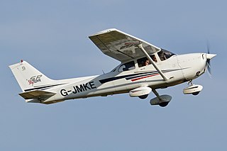
An aircraft is a vehicle that is able to fly by gaining support from the air. It counters the force of gravity by using either static lift or the dynamic lift of an airfoil, or, in a few cases, direct downward thrust from its engines. Common examples of aircraft include airplanes, rotorcraft, helicopters, airships, gliders, paramotors, and hot air balloons. Part 1 of Subchapter A of Chapter I of Title 14 of the U. S. Code of Federal Regulations states that aircraft "means a device that is used or intended to be used for flight in the air."

A vertical take-off and landing (VTOL) aircraft is one that can take off and land vertically without relying on a runway. This classification can include a variety of types of aircraft including helicopters as well as thrust-vectoring fixed-wing aircraft and other hybrid aircraft with powered rotors such as cyclogyros/cyclocopters and gyrodynes.
For fixed-wing aircraft, ground effect is the reduced aerodynamic drag that an aircraft's wings generate when they are close to a fixed surface. During takeoff, ground effect can cause the aircraft to "float" while below the recommended climb speed. The pilot can then fly just above the runway while the aircraft accelerates in ground effect until a safe climb speed is reached.
In fluid dynamics, angle of attack is the angle between a reference line on a body and the vector representing the relative motion between the body and the fluid through which it is moving. Angle of attack is the angle between the body's reference line and the oncoming flow. This article focuses on the most common application, the angle of attack of a wing or airfoil moving through air.

Aircraft flight control surfaces are aerodynamic devices allowing a pilot to adjust and control the aircraft's flight attitude.

In aircraft design and aerospace engineering, a high-lift device is a component or mechanism on an aircraft's wing that increases the amount of lift produced by the wing. The device may be a fixed component, or a movable mechanism which is deployed when required. Common movable high-lift devices include wing flaps and slats. Fixed devices include leading-edge slots, leading edge root extensions, and boundary layer control systems.
Aircraft flight mechanics are relevant to fixed wing and rotary wing (helicopters) aircraft. An aeroplane, is defined in ICAO Document 9110 as, "a power-driven heavier than air aircraft, deriving its lift chiefly from aerodynamic reactions on surface which remain fixed under given conditions of flight".
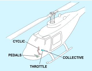
Helicopter flight controls are used to achieve and maintain controlled aerodynamic helicopter flight. Changes to the aircraft flight control system transmit mechanically to the rotor, producing aerodynamic effects on the rotor blades that make the helicopter move in a desired way. To tilt forward and back (pitch) or sideways (roll) requires that the controls alter the angle of attack of the main rotor blades cyclically during rotation, creating differing amounts of lift at different points in the cycle. To increase or decrease overall lift requires that the controls alter the angle of attack for all blades collectively by equal amounts at the same time, resulting in ascent, descent, acceleration and deceleration.

On a helicopter, the main rotor or rotor system is the combination of several rotary wings with a control system, that generates the aerodynamic lift force that supports the weight of the helicopter, and the thrust that counteracts aerodynamic drag in forward flight. Each main rotor is mounted on a vertical mast over the top of the helicopter, as opposed to a helicopter tail rotor, which connects through a combination of drive shaft(s) and gearboxes along the tail boom. The blade pitch is typically controlled by the pilot using the helicopter flight controls. Helicopters are one example of rotary-wing aircraft (rotorcraft). The name is derived from the Greek words helix, helik-, meaning spiral; and pteron meaning wing.

A rotary-wing aircraft, rotorwing aircraft or rotorcraft is a heavier-than-air aircraft with rotary wings that spin around a vertical mast to generate lift. Part 1 of Subchapter A of Chapter I of Title 14 of the U. S. Code of Federal Regulations states that rotorcraft "means a heavier-than-air aircraft that depends principally for its support in flight on the lift generated by one or more rotors." The assembly of several rotor blades mounted on a single mast is referred to as a rotor. The International Civil Aviation Organization (ICAO) defines a rotorcraft as "supported in flight by the reactions of the air on one or more rotors".
A convertiplane is defined by the Fédération Aéronautique Internationale as an aircraft which uses rotor power for vertical takeoff and landing (VTOL) and converts to fixed-wing lift in normal flight. In the US it is further classified as a sub-type of powered lift. In popular usage it sometimes includes any aircraft that converts in flight to change its method of obtaining lift.
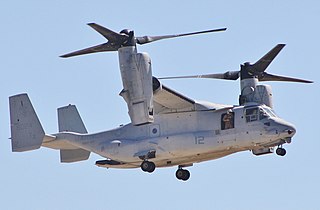
A powered lift aircraft takes off and lands vertically under engine power but uses a fixed wing for horizontal flight. Like helicopters, these aircraft do not need a long runway to take off and land, but they have a speed and performance similar to standard fixed-wing aircraft in combat or other situations.

The cyclogyro, or cyclocopter, is an aircraft configuration that uses a horizontal-axis cyclorotor as a rotor wing to provide lift and, sometimes, also propulsion and control. In principle, the cyclogyro is capable of vertical take off and landing and hovering performance, like a helicopter, while potentially benefiting from some of the advantages of a fixed-wing aircraft.

The wing configuration or planform of a fixed-wing aircraft is its arrangement of lifting and related surfaces.
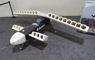
In aeronautics, Distributed propulsion is an arrangement in which the propulsive and related air flows are distributed over the aerodynamic surfaces of an aircraft. The purpose is to improve the craft's aerodynamic, propulsive and/or structural efficiency over an equivalent conventional design.
A rotor wing is a lifting rotor or wing which spins to provide aerodynamic lift. In general, a rotor may spin about an axis which is aligned substantially either vertically or side-to-side (spanwise). All three classes have been studied for use as lifting rotors and several variations have been flown on full-size aircraft, although only the vertical-axis rotary wing has become widespread on rotorcraft such as the helicopter.

The Tactical Robotics Cormorant, formerly AirMule or Mule, Israel Defense Forces (IDF) codename Pereira, is a flying car unmanned aerial vehicle (UAV) built by Tactical Robotics Ltd., a subsidiary of designer Rafi Yoeli's Urban Aeronautics Ltd., in Yavne, Israel. It will be used in search and rescue operations where it is too dangerous or inaccessible for a helicopter, such as evacuating people from the upper stories of burning buildings, or delivering and extracting police and soldiers while very close to structures, narrow streets, or through holes into confined spaces.
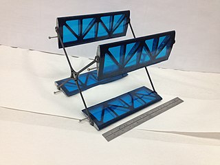
A cyclorotor, cycloidal rotor, cycloidal propeller or cyclogiro, is a fluid propulsion device that converts shaft power into the acceleration of a fluid using a rotating axis perpendicular to the direction of fluid motion. It uses several blades with a spanwise axis parallel to the axis of rotation and perpendicular to the direction of fluid motion. These blades are cyclically pitched twice per revolution to produce force in any direction normal to the axis of rotation. Cyclorotors are used for propulsion, lift, and control on air and water vehicles. An aircraft using cyclorotors as the primary source of lift, propulsion, and control is known as a cyclogyro or cyclocopter. A unique aspect is that it can change the magnitude and direction of thrust without the need of tilting any aircraft structures. The patented application, used on ships with particular actuation mechanisms both mechanical or hydraulic, is named after German company Voith Turbo.


