A transformer is a passive component that transfers electrical energy from one electrical circuit to another circuit, or multiple circuits. A varying current in any coil of the transformer produces a varying magnetic flux in the transformer's core, which induces a varying electromotive force across any other coils wound around the same core. Electrical energy can be transferred between separate coils without a metallic (conductive) connection between the two circuits. Faraday's law of induction, discovered in 1831, describes the induced voltage effect in any coil due to a changing magnetic flux encircled by the coil.

Electric power transmission is the bulk movement of electrical energy from a generating site, such as a power plant, to an electrical substation. The interconnected lines which facilitate this movement are known as a transmission network. This is distinct from the local wiring between high-voltage substations and customers, which is typically referred to as electric power distribution. The combined transmission and distribution network is part of electricity delivery, known as the electrical grid.

The characteristic impedance or surge impedance (usually written Z0) of a uniform transmission line is the ratio of the amplitudes of voltage and current of a single wave propagating along the line; that is, a wave travelling in one direction in the absence of reflections in the other direction. Alternatively, and equivalently, it can be defined as the input impedance of a transmission line when its length is infinite. Characteristic impedance is determined by the geometry and materials of the transmission line and, for a uniform line, is not dependent on its length. The SI unit of characteristic impedance is the ohm.

A loading coil or load coil is an inductor that is inserted into an electronic circuit to increase its inductance. The term originated in the 19th century for inductors used to prevent signal distortion in long-distance telegraph transmission cables. The term is also used for inductors in radio antennas, or between the antenna and its feedline, to make an electrically short antenna resonant at its operating frequency.

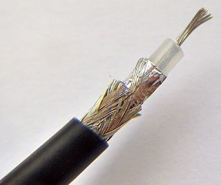
In electrical engineering, a transmission line is a specialized cable or other structure designed to conduct electromagnetic waves in a contained manner. The term applies when the conductors are long enough that the wave nature of the transmission must be taken into account. This applies especially to radio-frequency engineering because the short wavelengths mean that wave phenomena arise over very short distances. However, the theory of transmission lines was historically developed to explain phenomena on very long telegraph lines, especially submarine telegraph cables.

In electrical engineering, impedance is the opposition to alternating current presented by the combined effect of resistance and reactance in a circuit.
In electrical circuits, reactance is the opposition presented to alternating current by inductance or capacitance. Greater reactance gives smaller current for the same applied voltage. Reactance is similar to resistance in this respect, but differs in that reactance does not lead to dissipation of electrical energy as heat. Instead, energy is momentarily stored in the reactance, and a quarter-cycle later returned to the circuit, whereas a resistance continuously loses energy.

In electronics, negative resistance (NR) is a property of some electrical circuits and devices in which an increase in voltage across the device's terminals results in a decrease in electric current through it.
A flexible alternating current transmission system (FACTS) is a system composed of static equipment used for the alternating current (AC) transmission of electrical energy. It is meant to enhance controllability and increase power transfer capability of the network. It is generally a power electronics-based system.

In electronics, impedance matching is the practice of designing or adjusting the input impedance or output impedance of an electrical device for a desired value. Often, the desired value is selected to maximize power transfer or minimize signal reflection. Signals on a transmission line will be transmitted without reflections if the transmission line is terminated with a matching impedance.

An antenna tuner is a device that is inserted between a radio transmitter and its antenna; when properly adjusted (tuned) it improves power transfer by matching the impedance of the radio to the impedance of the antenna, or the feedline which connects the antenna to the transmitter.

The input impedance of an electrical network is the measure of the opposition to current (impedance), both static (resistance) and dynamic (reactance), into the load network that is external to the electrical source. The input admittance (1/impedance) is a measure of the load's propensity to draw current. The source network is the portion of the network that transmits power, and the load network is the portion of the network that consumes power.
In electrical engineering, particularly power engineering, voltage regulation is a measure of change in the voltage magnitude between the sending and receiving end of a component, such as a transmission or distribution line. Voltage regulation describes the ability of a system to provide near constant voltage over a wide range of load conditions. The term may refer to a passive property that results in more or less voltage drop under various load conditions, or to the active intervention with devices for the specific purpose of adjusting voltage.

An overhead power line is a structure used in electric power transmission and distribution to transmit electrical energy across large distances. It consists of one or more uninsulated electrical cables suspended by towers or poles.
The Heaviside condition, named for Oliver Heaviside (1850–1925), is the condition an electrical transmission line must meet in order for there to be no distortion of a transmitted signal. Also known as the distortionless condition, it can be used to improve the performance of a transmission line by adding loading to the cable.

Capacitors are manufactured in many forms, styles, lengths, girths, and from many materials. They all contain at least two electrical conductors separated by an insulating layer. Capacitors are widely used as parts of electrical circuits in many common electrical devices.
The telegrapher's equations are a pair of coupled, linear partial differential equations that describe the voltage and current on an electrical transmission line with distance and time. The equations come from Oliver Heaviside who developed the transmission line model starting with an August 1876 paper, On the Extra Current. The model demonstrates that the electromagnetic waves can be reflected on the wire, and that wave patterns can form along the line.

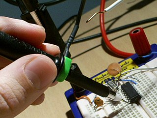
A test probe is a physical device used to connect electronic test equipment to a device under test (DUT). Test probes range from very simple, robust devices to complex probes that are sophisticated, expensive, and fragile. Specific types include test prods, oscilloscope probes and current probes. A test probe is often supplied as a test lead, which includes the probe, cable and terminating connector.

The gyrator–capacitor model - sometimes also the capacitor-permeance model - is a lumped-element model for magnetic circuits, that can be used in place of the more common resistance–reluctance model. The model makes permeance elements analogous to electrical capacitance rather than electrical resistance. Windings are represented as gyrators, interfacing between the electrical circuit and the magnetic model.

Performance modelling is the abstraction of a real system into a simplified representation to enable the prediction of performance. The creation of a model can provide insight into how a proposed or actual system will or does work. This can, however, point towards different things to people belonging to different fields of work.


