
A bogie comprises two or more wheelsets, in a frame, attached under a vehicle by a pivot. Bogies take various forms in various modes of transport. A bogie may remain normally attached or be quickly detachable. It may include suspension components within it, or be solid and in turn be suspended. It may be mounted on a swivel, as traditionally on a railway carriage or locomotive, additionally jointed and sprung, or held in place by other means.

A rack railway is a steep grade railway with a toothed rack rail, usually between the running rails. The trains are fitted with one or more cog wheels or pinions that mesh with this rack rail. This allows the trains to operate on steep gradients of 100% or more, well above the 10% maximum for friction-based rail. The rack and pinion mechanism also provides more controlled braking and reduces the effects of snow or ice on the rails. Most rack railways are mountain railways, although a few are transit railways or tramways built to overcome a steep gradient in an urban environment. The first cog railway was the Middleton Railway between Middleton and Leeds in West Yorkshire, England, United Kingdom, where the first commercially successful steam locomotive, Salamanca, ran in 1812. This used a rack and pinion system designed and patented in 1811 by John Blenkinsop.

A railroad switch (AE), turnout, or [set of] points (CE) is a mechanical installation enabling railway trains to be guided from one track to another, such as at a railway junction or where a spur or siding branches off.
Rail transport terms are a form of technical terminology applied to railways. Although many terms are uniform across different nations and companies, they are by no means universal, with differences often originating from parallel development of rail transport systems in different parts of the world, and in the national origins of the engineers and managers who built the inaugural rail infrastructure. An example is the term railroad, used in North America, and railway, generally used in English-speaking countries outside North America and by the International Union of Railways. In English-speaking countries outside the United Kingdom, a mixture of US and UK terms may exist.
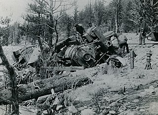
In rail transport, a derailment is a type of train wreck that occurs when a rail vehicle such as a train comes off its rails. Although many derailments are minor, all result in temporary disruption of the proper operation of the railway system and they are a potentially serious hazard.

An adhesion railway relies on adhesion traction to move the train, and is the most widespread and common type of railway in the world. Adhesion traction is the friction between the drive wheels and the steel rail. Since the vast majority of railways are adhesion railways, the term adhesion railway is used only when it is necessary to distinguish adhesion railways from railways moved by other means, such as by a stationary engine pulling on a cable attached to the cars or by a pinion meshing with a rack.
A wheel speed sensor (WSS) or vehicle speed sensor (VSS) is a type of tachometer. It is a sender device used for reading the speed of a vehicle's wheel rotation. It usually consists of a toothed ring and pickup.

A swingnose crossing or moveable point frog is a device used at a railroad switch to eliminate the gap at the common crossing which can cause damage and noise.
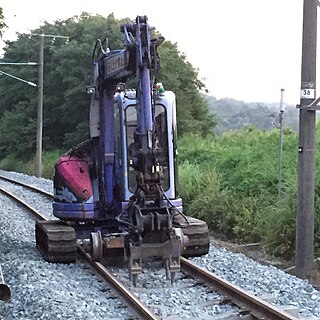
A road–rail vehicle or a rail–road vehicle is a dual-mode vehicle which can operate both on rail tracks and roads. They are also known as two-way vehicles, hi-rail, and rail and road vehicles.
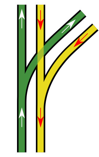
A level junction is a railway junction that has a track configuration in which merging or crossing railroad lines provide track connections with each other that require trains to cross over in front of opposing traffic at grade.
Tramway track is used on tramways or light rail operations. As with standard rail tracks, tram tracks have two parallel steel rails, the distance between the heads of the rails being the track gauge. When there is no need for pedestrians or road vehicles to traverse the track, conventional flat-bottom rail is used. However, when such traffic exists, such as in urban streets, grooved rails are used.

A double junction is a railway junction where a double-track railway splits into two double track lines. Usually, one line is the main line and carries traffic through the junction at normal speed, while the other track is a branch line that carries traffic through the junction at reduced speed.

An axle counter is a system used in railway signalling to detect the clear or occupied status of a section of track between two points. The system generally consists of a wheel sensor and an evaluation unit for counting the axles of the train both into and out of the section. They are often used to replace a track circuit.

Hunting oscillation is a self-oscillation, usually unwanted, about an equilibrium. The expression came into use in the 19th century and describes how a system "hunts" for equilibrium. The expression is used to describe phenomena in such diverse fields as electronics, aviation, biology, and railway engineering.
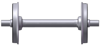
A wheelset is a pair of railroad vehicle wheels mounted rigidly on an axle allowing both wheels to rotate together. Wheelsets are often mounted in a bogie – a pivoted frame assembly holding at least two wheelsets – at each end of the vehicle. Most modern freight cars and passenger cars have bogies each with two wheelsets, but three wheelsets are used in bogies of freight cars that carry heavy loads, and three-wheelset bogies are under some passenger cars. Four-wheeled goods wagons that were once near-universal in Europe and Great Britain and their colonies have only two wheelsets; in recent decades such vehicles have become less common as trainloads have become heavier.
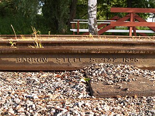
The rail profile is the cross sectional shape of a railway rail, perpendicular to its length.

The Ewing System is a balancing monorail system developed in the late 19th century by British inventor W. J. Ewing. It is not to be confused with the much later system patented by Robert W. Ewing.

In automobiles, the axle track is the distance between the hub flanges on an axle. Wheel track, track width or simply track refers to the distance between the centerline of two wheels on the same axle. In the case of an axle with dual wheels, the centerline of the dual wheel assembly is used for the wheel track specification. Axle and wheel track are commonly measured in millimetres or inches.

A railway or railroad is a track on which the vehicle travels over two parallel steel bars, called rails. The rails support and guide the wheels of the vehicles, which are traditionally either trains or trams. Modern light rail is a relatively new innovation which combines aspects of those two modes of transport. However fundamental differences in the track and wheel design are important, especially where trams or light railways and trains have to share a section of track, as sometimes happens in congested areas.

A train wheel or rail wheel is a type of wheel specially designed for use on railway tracks. The wheel acts as a rolling component, typically press fitted onto an axle and mounted directly on a railway carriage or locomotive, or indirectly on a bogie, also called a truck. The powered wheels under the locomotive are called driving wheels. Wheels are initially cast or forged and then heat-treated to have a specific hardness. New wheels are machined using a lathe to a standardized shape, called a profile, before being installed onto an axle. All wheel profiles are regularly checked to ensure proper interaction between the wheel and the rail. Incorrectly profiled wheels and worn wheels can increase rolling resistance, reduce energy efficiency and may even cause a derailment. The International Union of Railways has defined a standard wheel diameter of 920 mm (36 in), although smaller sizes are used in some rapid transit railway systems and on ro-ro carriages.


