
Flight instruments are the instruments in the cockpit of an aircraft that provide the pilot with data about the flight situation of that aircraft, such as altitude, airspeed, vertical speed, heading and much more other crucial information in flight. They improve safety by allowing the pilot to fly the aircraft in level flight, and make turns, without a reference outside the aircraft such as the horizon. Visual flight rules (VFR) require an airspeed indicator, an altimeter, and a compass or other suitable magnetic direction indicator. Instrument flight rules (IFR) additionally require a gyroscopic pitch-bank, direction and rate of turn indicator, plus a slip-skid indicator, adjustable altimeter, and a clock. Flight into instrument meteorological conditions (IMC) require radio navigation instruments for precise takeoffs and landings.

A cockpit or flight deck is the area, on the front part of an aircraft, spacecraft, or submersible, from which a pilot controls the vehicle.
Aviation is the design, development, production, operation, and use of aircraft, especially heavier-than-air aircraft. Articles related to aviation include:
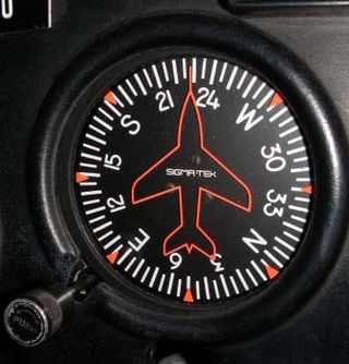
The heading indicator (HI), also known as a directional gyro (DG) or direction indicator (DI), is a flight instrument used in an aircraft to inform the pilot of the aircraft's heading.

The attitude indicator (AI), formerly known as the gyro horizon or artificial horizon, is a flight instrument that informs the pilot of the aircraft orientation relative to Earth's horizon, and gives an immediate indication of the smallest orientation change. The miniature aircraft and horizon bar mimic the relationship of the aircraft relative to the actual horizon. It is a primary instrument for flight in instrument meteorological conditions.

An autopilot is a system used to control the path of a vehicle without requiring constant manual control by a human operator. Autopilots do not replace human operators. Instead, the autopilot assists the operator's control of the vehicle, allowing the operator to focus on broader aspects of operations.

A head-up display, or heads-up display, also known as a HUD or head-up guidance system (HGS), is any transparent display that presents data without requiring users to look away from their usual viewpoints. The origin of the name stems from a pilot being able to view information with the head positioned "up" and looking forward, instead of angled down looking at lower instruments. A HUD also has the advantage that the pilot's eyes do not need to refocus to view the outside after looking at the optically nearer instruments.
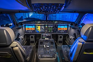
A glass cockpit is an aircraft cockpit that features an array of electronic (digital) flight instrument displays, typically large LCD screens, rather than traditional analog dials and gauges. While a traditional cockpit relies on numerous mechanical gauges to display information, a glass cockpit uses several multi-function displays and a primary flight display driven by flight management systems, that can be adjusted to show flight information as needed. This simplifies aircraft operation and navigation and allows pilots to focus only on the most pertinent information. They are also popular with airline companies as they usually eliminate the need for a flight engineer, saving costs. In recent years the technology has also become widely available in small aircraft.
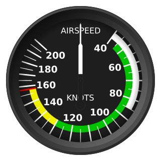
Indicated airspeed (IAS) is the airspeed of an aircraft as measured by its pitot-static system and displayed by the airspeed indicator (ASI). This is the pilots' primary airspeed reference.

An instrument landing system localizer, or simply localizer, is a system of horizontal guidance in the instrument landing system, which is used to guide aircraft along the axis of the runway.

In aviation, an electronic flight instrument system (EFIS) is a flight instrument display system in an aircraft cockpit that displays flight data electronically rather than electromechanically. An EFIS normally consists of a primary flight display (PFD), multi-function display (MFD), and an engine indicating and crew alerting system (EICAS) display. Early EFIS models used cathode-ray tube (CRT) displays, but liquid crystal displays (LCD) are now more common. The complex electromechanical attitude director indicator (ADI) and horizontal situation indicator (HSI) were the first candidates for replacement by EFIS. Now, however, few flight deck instruments cannot be replaced by an electronic display.

The Garmin G1000 is an electronic flight instrument system (EFIS) typically composed of two display units, one serving as a primary flight display, and one as a multi-function display. Manufactured by Garmin Aviation, it serves as a replacement for most conventional flight instruments and avionics. Introduced in June 2004, the system has since become one of the most popular integrated glass cockpit solutions for general aviation and business aircraft.

An air data computer (ADC) or central air data computer (CADC) computes altitude, vertical speed, air speed, and Mach number from pressure and temperature inputs. It is an essential avionics component found in modern aircraft. This computer, rather than individual instruments, can determine the calibrated airspeed, Mach number, altitude, and altitude trend data from an aircraft's pitot-static system. In some very high-speed aircraft such as the Space Shuttle, equivalent airspeed is calculated instead of calibrated airspeed. Air data computers usually also have an input of total air temperature. This enables the computation of static air temperature and true airspeed.
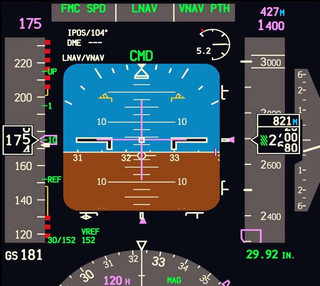
A primary flight display or PFD is a modern aircraft instrument dedicated to flight information. Much like multi-function displays, primary flight displays are built around a Liquid-crystal display or CRT display device. Representations of older six pack or "steam gauge" instruments are combined on one compact display, simplifying pilot workflow and streamlining cockpit layouts.

The horizontal situation indicator is an aircraft flight instrument normally mounted below the artificial horizon in place of a conventional heading indicator. It combines a heading indicator with a VHF omnidirectional range-instrument landing system (VOR-ILS) display. This reduces pilot workload by lessening the number of elements in the pilot's instrument scan to the six basic flight instruments. Among other advantages, the HSI offers freedom from the confusion of reverse sensing on an instrument landing system localizer back course approach. As long as the needle is set to the localizer front course, the instrument will indicate whether to fly left or right, in either direction of travel.
An Air Data Inertial Reference Unit (ADIRU) is a key component of the integrated Air Data Inertial Reference System (ADIRS), which supplies air data and inertial reference information to the pilots' electronic flight instrument system displays as well as other systems on the aircraft such as the engines, autopilot, aircraft flight control system and landing gear systems. An ADIRU acts as a single, fault tolerant source of navigational data for both pilots of an aircraft. It may be complemented by a secondary attitude air data reference unit (SAARU), as in the Boeing 777 design.
L-3 SmartDeck - is a fully integrated cockpit system originally developed by L-3 Avionics Systems. and acquired in 2010 by Esterline CMC Electronics through an exclusive licensing agreement.

A flight control mode or flight control law is a computer software algorithm that transforms the movement of the yoke or joystick, made by an aircraft pilot, into movements of the aircraft control surfaces. The control surface movements depend on which of several modes the flight computer is in. In aircraft in which the flight control system is fly-by-wire, the movements the pilot makes to the yoke or joystick in the cockpit, to control the flight, are converted to electronic signals, which are transmitted to the flight control computers that determine how to move each control surface to provide the aircraft movement the pilot ordered.

Loganair Flight 6780 was a scheduled domestic flight from Aberdeen Airport to Sumburgh Airport in the Shetland Islands, Scotland. On 15 December 2014, the Saab 2000 operating the flight was struck by lightning during the approach, and then plunged faster than the aircraft's maximum operating speed. The aircraft came within 1,100 feet (340 m) of the North Sea before the pilots recovered and returned to Aberdeen. All 33 passengers and crew were unharmed.

A flight control computer (FCC) is a primary component of the avionics system found in fly-by-wire aircraft. It is a specialized computer system that can create artificial flight characteristics and improve handling characteristics by automating a variety of in-flight tasks which reduce the workload on the cockpit flight crew.


