This article includes a list of references, related reading, or external links, but its sources remain unclear because it lacks inline citations .(May 2023) |
Friis formula or Friis's formula (sometimes Friis' formula), named after Danish-American electrical engineer Harald T. Friis, is either of two formulas used in telecommunications engineering to calculate the signal-to-noise ratio of a multistage amplifier. One relates to noise factor while the other relates to noise temperature.
Friis's formula is used to calculate the total noise factor of a cascade of stages, each with its own noise factor and power gain (assuming that the impedances are matched at each stage). The total noise factor can then be used to calculate the total noise figure. The total noise factor is given as
where and are the noise factor and available power gain, respectively, of the i-th stage, and n is the number of stages. Both magnitudes are expressed as ratios, not in decibels.
An important consequence of this formula is that the overall noise figure of a radio receiver is primarily established by the noise figure of its first amplifying stage. Subsequent stages have a diminishing effect on signal-to-noise ratio. For this reason, the first stage amplifier in a receiver is often called the low-noise amplifier (LNA). The overall receiver noise "factor" is then
where is the overall noise factor of the subsequent stages. According to the equation, the overall noise factor, , is dominated by the noise factor of the LNA, , if the gain is sufficiently high. The resultant Noise Figure expressed in dB is:
For a derivation of Friis' formula for the case of three cascaded amplifiers () consider the image below.
A source outputs a signal of power and noise of power . Therefore the SNR at the input of the receiver chain is . The signal of power gets amplified by all three amplifiers. Thus the signal power at the output of the third amplifier is . The noise power at the output of the amplifier chain consists of four parts:
Therefore the total noise power at the output of the amplifier chain equals
and the SNR at the output of the amplifier chain equals
The total noise factor may now be calculated as quotient of the input and output SNR:
Using the definitions of the noise factors of the amplifiers we get the final result:
General derivation for a cascade of amplifiers:
The total noise figure is given as the relation of the signal-to-noise ratio at the cascade input to the signal-to-noise ratio at the cascade output as
.
The total input power of the -th amplifier in the cascade (noise and signal) is . It is amplified according to the amplifier's power gain . Additionally, the amplifier adds noise with power . Thus the output power of the -th amplifier is . For the entire cascade, one obtains the total output power
The output signal power thus rewrites as
whereas the output noise power can be written as
Substituting these results into the total noise figure leads to
Now, using as the noise figure of the individual -th amplifier, one obtains
Friis's formula can be equivalently expressed in terms of noise temperature:
Noise figure (NF) and noise factor (F) are figures of merit that indicate degradation of the signal-to-noise ratio (SNR) that is caused by components in a signal chain. These figures of merit are used to evaluate the performance of an amplifier or a radio receiver, with lower values indicating better performance.
In electronics, noise temperature is one way of expressing the level of available noise power introduced by a component or source. The power spectral density of the noise is expressed in terms of the temperature that would produce that level of Johnson–Nyquist noise, thus:
Signal-to-noise ratio is a measure used in science and engineering that compares the level of a desired signal to the level of background noise. SNR is defined as the ratio of signal power to noise power, often expressed in decibels. A ratio higher than 1:1 indicates more signal than noise.
The total harmonic distortion is a measurement of the harmonic distortion present in a signal and is defined as the ratio of the sum of the powers of all harmonic components to the power of the fundamental frequency. Distortion factor, a closely related term, is sometimes used as a synonym.
A rectifier is an electrical device that converts alternating current (AC), which periodically reverses direction, to direct current (DC), which flows in only one direction. The reverse operation is performed by an inverter.
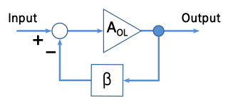
A negative-feedback amplifier is an electronic amplifier that subtracts a fraction of its output from its input, so that negative feedback opposes the original signal. The applied negative feedback can improve its performance and reduces sensitivity to parameter variations due to manufacturing or environment. Because of these advantages, many amplifiers and control systems use negative feedback.
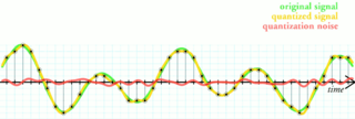
Quantization, in mathematics and digital signal processing, is the process of mapping input values from a large set to output values in a (countable) smaller set, often with a finite number of elements. Rounding and truncation are typical examples of quantization processes. Quantization is involved to some degree in nearly all digital signal processing, as the process of representing a signal in digital form ordinarily involves rounding. Quantization also forms the core of essentially all lossy compression algorithms.
The sensitivity of an electronic device, such as a communications system receiver, or detection device, such as a PIN diode, is the minimum magnitude of input signal required to produce a specified output signal having a specified signal-to-noise ratio, or other specified criteria.
The asymptotic gain model is a representation of the gain of negative feedback amplifiers given by the asymptotic gain relation:
In signal processing, a matched filter is obtained by correlating a known delayed signal, or template, with an unknown signal to detect the presence of the template in the unknown signal. This is equivalent to convolving the unknown signal with a conjugated time-reversed version of the template. The matched filter is the optimal linear filter for maximizing the signal-to-noise ratio (SNR) in the presence of additive stochastic noise.
In quantum field theory, the Lehmann–Symanzik–Zimmermann (LSZ) reduction formula is a method to calculate S-matrix elements from the time-ordered correlation functions of a quantum field theory. It is a step of the path that starts from the Lagrangian of some quantum field theory and leads to prediction of measurable quantities. It is named after the three German physicists Harry Lehmann, Kurt Symanzik and Wolfhart Zimmermann.
Scattering parameters or S-parameters describe the electrical behavior of linear electrical networks when undergoing various steady state stimuli by electrical signals.
This article illustrates some typical operational amplifier applications. A non-ideal operational amplifier's equivalent circuit has a finite input impedance, a non-zero output impedance, and a finite gain. A real op-amp has a number of non-ideal features as shown in the diagram, but here a simplified schematic notation is used, many details such as device selection and power supply connections are not shown. Operational amplifiers are optimised for use with negative feedback, and this article discusses only negative-feedback applications. When positive feedback is required, a comparator is usually more appropriate. See Comparator applications for further information.
Signal-to-quantization-noise ratio is widely used quality measure in analysing digitizing schemes such as pulse-code modulation (PCM). The SQNR reflects the relationship between the maximum nominal signal strength and the quantization error introduced in the analog-to-digital conversion.
A phase-shift oscillator is a linear electronic oscillator circuit that produces a sine wave output. It consists of an inverting amplifier element such as a transistor or op amp with its output fed back to its input through a phase-shift network consisting of resistors and capacitors in a ladder network. The feedback network 'shifts' the phase of the amplifier output by 180 degrees at the oscillation frequency to give positive feedback. Phase-shift oscillators are often used at audio frequency as audio oscillators.
In digital photography, the image sensor format is the shape and size of the image sensor.
A Tower Mounted Amplifier (TMA), or Mast Head Amplifier (MHA), is a low-noise amplifier (LNA) mounted as close as practical to the antenna in mobile masts or base transceiver stations. A TMA reduces the base transceiver station noise figure (NF) and therefore improves its overall sensitivity; in other words the mobile mast is able to receive weaker signals. The power to feed the amplifier is usually a DC component on the same coaxial cable that feeds the antenna, otherwise an extra power cable has to be run to the TMA/MHA to supply it with power.
Signal averaging is a signal processing technique applied in the time domain, intended to increase the strength of a signal relative to noise that is obscuring it. By averaging a set of replicate measurements, the signal-to-noise ratio (SNR) will be increased, ideally in proportion to the square root of the number of measurements.
In the mathematical field of algebraic number theory, the concept of principalization refers to a situation when, given an extension of algebraic number fields, some ideal of the ring of integers of the smaller field isn't principal but its extension to the ring of integers of the larger field is. Its study has origins in the work of Ernst Kummer on ideal numbers from the 1840s, who in particular proved that for every algebraic number field there exists an extension number field such that all ideals of the ring of integers of the base field become principal when extended to the larger field. In 1897 David Hilbert conjectured that the maximal abelian unramified extension of the base field, which was later called the Hilbert class field of the given base field, is such an extension. This conjecture, now known as principal ideal theorem, was proved by Philipp Furtwängler in 1930 after it had been translated from number theory to group theory by Emil Artin in 1929, who made use of his general reciprocity law to establish the reformulation. Since this long desired proof was achieved by means of Artin transfers of non-abelian groups with derived length two, several investigators tried to exploit the theory of such groups further to obtain additional information on the principalization in intermediate fields between the base field and its Hilbert class field. The first contributions in this direction are due to Arnold Scholz and Olga Taussky in 1934, who coined the synonym capitulation for principalization. Another independent access to the principalization problem via Galois cohomology of unit groups is also due to Hilbert and goes back to the chapter on cyclic extensions of number fields of prime degree in his number report, which culminates in the famous Theorem 94.
An RF chain is a cascade of electronic components and sub-units which may include amplifiers, filters, mixers, attenuators and detectors. It can take many forms, for example, as a wide-band receiver-detector for electronic warfare (EW) applications, as a tunable narrow-band receiver for communications purposes, as a repeater in signal distribution systems, or as an amplifier and up-converters for a transmitter-driver. In this article, the term RF covers the frequency range "Medium Frequencies" up to "Microwave Frequencies", i.e. from 100 kHz to 20 GHz.