Related Research Articles
The unified modeling language (UML) is a general-purpose visual modeling language that is intended to provide a standard way to visualize the design of a system.
In software and systems engineering, the phrase use case is a polyseme with two senses:
- A usage scenario for a piece of software; often used in the plural to suggest situations where a piece of software may be useful.
- A potential scenario in which a system receives an external request and responds to it.
A modeling language is any artificial language that can be used to express data, information or knowledge or systems in a structure that is defined by a consistent set of rules. The rules are used for interpretation of the meaning of components in the structure Programing language.

In systems engineering and software engineering, requirements analysis focuses on the tasks that determine the needs or conditions to meet the new or altered product or project, taking account of the possibly conflicting requirements of the various stakeholders, analyzing, documenting, validating and managing software or system requirements.

Business process modeling (BPM) in business process management and systems engineering is the activity of representing processes of an enterprise, so that the current business processes may be analyzed, improved, and automated. BPM is typically performed by business analysts, who provide expertise in the modeling discipline; by subject matter experts, who have specialized knowledge of the processes being modeled; or more commonly by a team comprising both. Alternatively, the process model can be derived directly from events' logs using process mining tools.
A UML tool is a software application that supports some or all of the notation and semantics associated with the Unified Modeling Language (UML), which is the industry standard general-purpose modeling language for software engineering.
In computing, a scenario is a narrative of foreseeable interactions of user roles and the technical system, which usually includes computer hardware and software.
Object-oriented analysis and design (OOAD) is a technical approach for analyzing and designing an application, system, or business by applying object-oriented programming, as well as using visual modeling throughout the software development process to guide stakeholder communication and product quality.
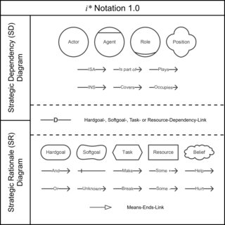
i* or i* framework is a modeling language suitable for an early phase of system modeling in order to understand the problem domain. i* modeling language allows to model both as-is and to-be situations. The name i* refers to the notion of distributed intentionality which underlines the framework. It is an approach originally developed for modelling and reasoning about organizational environments and their information systems composed of heterogeneous actors with different, often competing, goals that depend on each other to undertake their tasks and achieve these goals. It covers both actor-oriented and Goal modeling. i* models answer the question WHO and WHY, not what.
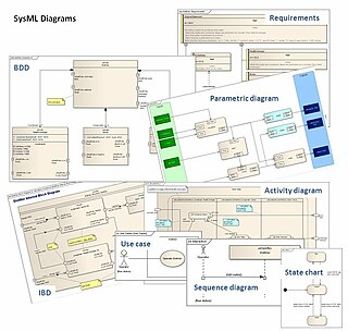
The systems modeling language (SysML) is a general-purpose modeling language for systems engineering applications. It supports the specification, analysis, design, verification and validation of a broad range of systems and systems-of-systems.

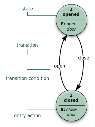
In object-oriented programming, an object diagram in the Unified Modeling Language (UML) is a diagram that shows a complete or partial view of the structure of a modeled system at a specific time.
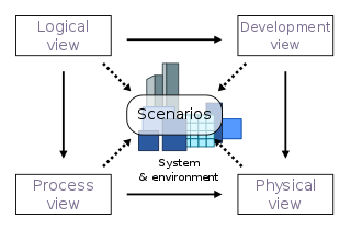
4+1 is a view model used for "describing the architecture of software-intensive systems, based on the use of multiple, concurrent views". The views are used to describe the system from the viewpoint of different stakeholders, such as end-users, developers, system engineers, and project managers. The four views of the model are logical, development, process and physical view. In addition, selected use cases or scenarios are used to illustrate the architecture serving as the 'plus one' view. Hence, the model contains 4+1 views:
KAOS, is a goal-oriented software requirements capturing approach in requirements engineering. It is a specific Goal modeling method; another is i*. It allows for requirements to be calculated from goal diagrams. KAOS stands for Knowledge Acquisition in automated specification or Keep All Objectives Satisfied.
In requirements engineering, requirements elicitation is the practice of researching and discovering the requirements of a system from users, customers, and other stakeholders. The practice is also sometimes referred to as "requirement gathering".

Misuse case is a business process modeling tool used in the software development industry. The term Misuse Case or mis-use case is derived from and is the inverse of use case. The term was first used in the 1990s by Guttorm Sindre of the Norwegian University of Science and Technology, and Andreas L. Opdahl of the University of Bergen, Norway. It describes the process of executing a malicious act against a system, while use case can be used to describe any action taken by the system.
Enterprise engineering is the body of knowledge, principles, and practices used to design all or part of an enterprise. An enterprise is a complex socio-technical system that comprises people, information, and technology that interact with each other and their environment in support of a common mission. One definition is: "an enterprise life-cycle oriented discipline for the identification, design, and implementation of enterprises and their continuous evolution", supported by enterprise modelling. The discipline examines each aspect of the enterprise, including business processes, information flows, material flows, and organizational structure. Enterprise engineering may focus on the design of the enterprise as a whole, or on the design and integration of certain business components.
Abuse case is a specification model for security requirements used in the software development industry. The term Abuse Case is an adaptation of use case. The term was introduced by John McDermott and Chris Fox in 1999, while working at Computer Science Department of the James Madison University. As defined by its authors, an abuse case is a type of complete interaction between a system and one or more actors, where the results of the interaction are harmful to the system, one of the actors, or one of the stakeholders in the system. We cannot define completeness just in terms of coherent transactions between actors and the system. Instead, we must define abuse in terms of interactions that result in actual harm. A complete abuse case defines an interaction between an actor and the system that results in harm to a resource associated with one of the actors, one of the stakeholders, or the system itself.
UML is a modeling language used by software developers. UML can be used to develop diagrams and provide users (programmers) with ready-to-use, expressive modeling examples. Some UML tools generate program language code from UML. UML can be used for modeling a system independent of a platform language. UML is a graphical language for visualizing, specifying, constructing, and documenting information about software-intensive systems. UML gives a standard way to write a system model, covering conceptual ideas. With an understanding of modeling, the use and application of UML can make the software development process more efficient.
John Mylopoulos is a Greek-Canadian computer scientist, Professor at the University of Toronto, Canada, and at the University of Trento, Italy. He is known for his work in the field of conceptual modeling, specifically the development an agent-oriented software development methodology. called TROPOS.
Axel van Lamsweerde is a Belgian computer scientist and Professor of Computing Science at the Universite catholique de Louvain, known for his work on requirements engineering and the development of the KAOS goal-oriented modeling language.
References
- ↑ Alexander and Beus-Dukic, 2009. Pages 17-18
- ↑ Lin Liu and Eric Yu (2003). "Designing information systems in social context: a goal and scenario modelling approach" (PDF). University of Toronto. Archived from the original (PDF) on February 5, 2005.
- ↑ Ellis-Braithwaite, R.; Lock, R.; Dawson, R.; Haque B. (2013). "Towards an Approach for Analysing the Strategic Alignment of Software Requirements using Quantified Goal Graphs". International Journal on Advances in Software. 6: 119–130. arXiv: 1307.2580 . Bibcode:2013arXiv1307.2580E.
- ↑ E. Yu, "Towards Modelling and Reasoning Support for Early-Phase Requirements Engineering", 1997 IEEE
- 1 2 3 Eric Yu and John Mylopoulos. "Why Goal-Oriented Requirements Engineering". University of Toronto.
- ↑ K.Pohl and P. Haumer, "Modelling Contextual Information about Scenarios", Proc. 3rd Int. Workshop on Requirements Engineering: Foundations of Software Quality REFSQ ’97, Barcelona, Catalonia, Spain, June 1997 pp. 187-204.
- ↑ Yu et al, 2011.
- 1 2 van Lamsweerde, 2009.
- ↑ Fowler, 2004. Pages 99-105
- ↑ Rolland, Colette; Prakash, Naveen; Benjamen, Adolphe (1999). "A Multi-Model View of Process Modelling" (PDF). Requirements Engineering. 4 (4): 169–187. doi:10.1007/s007660050018. S2CID 6988662.
- ↑ GSN Community Standard
- ↑ Feodoroff, R. (2016). "Intentional enterprise architecture". 2016 Annual IEEE Systems Conference (SysCon). pp. 1–8. doi:10.1109/SYSCON.2016.7490555. ISBN 978-1-4673-9519-9. S2CID 206586399.
- ↑ Yu, Eric (September 6, 2011). "i*". i*: an agent- and goal-oriented modelling framework. University of Toronto. Retrieved December 17, 2011.
- ↑ Alexander and Beus-Dukic, 2009. Page 121
- ↑ Cockburn, 2001. Page 62
- ↑ Cockburn, 2001. Page 221
- ↑ Alexander and Maiden, 2004. Chapter 7. Pages 119-139.