An object-modeling language is a standardized set of symbols used to model a software system using an object-oriented framework. The symbols can be either informal or formal ranging from predefined graphical templates to formal object models defined by grammars and specifications.

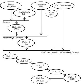
The unified modeling language (UML) is a general-purpose visual modeling language that is intended to provide a standard way to visualize the design of a system.
The rational unified process (RUP) is an iterative software development process framework created by the Rational Software Corporation, a division of IBM since 2003. RUP is not a single concrete prescriptive process, but rather an adaptable process framework, intended to be tailored by the development organizations and software project teams that will select the elements of the process that are appropriate for their needs. RUP is a specific implementation of the Unified Process.
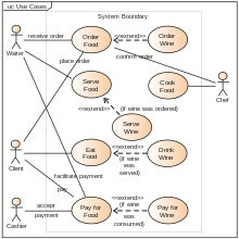
In software and systems engineering, the phrase use case is a polyseme with two senses:
- A usage scenario for a piece of software; often used in the plural to suggest situations where a piece of software may be useful.
- A potential scenario in which a system receives an external request and responds to it.
Model-driven architecture (MDA) is a software design approach for the development of software systems. It provides a set of guidelines for the structuring of specifications, which are expressed as models. Model Driven Architecture is a kind of domain engineering, and supports model-driven engineering of software systems. It was launched by the Object Management Group (OMG) in 2001.

In software engineering, a sequence diagram shows process interactions arranged in time sequence. This diagram depicts the processes and objects involved and the sequence of messages exchanged as needed to carry out the functionality. Sequence diagrams are typically associated with use case realizations in the 4+1 architectural view model of the system under development. Sequence diagrams are sometimes called event diagrams or event scenarios.
A UML tool is a software application that supports some or all of the notation and semantics associated with the Unified Modeling Language (UML), which is the industry standard general-purpose modeling language for software engineering.

In software engineering, a class diagram in the Unified Modeling Language (UML) is a type of static structure diagram that describes the structure of a system by showing the system's classes, their attributes, operations, and the relationships among objects.
Object-oriented analysis and design (OOAD) is a technical approach for analyzing and designing an application, system, or business by applying object-oriented programming, as well as using visual modeling throughout the software development process to guide stakeholder communication and product quality.

A package diagram in the Unified Modeling Language depicts "specializations for Models and for Profiles that organize extensions to UML."
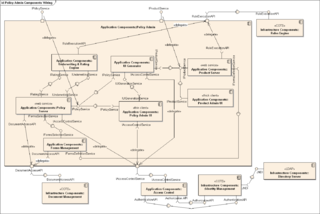
In Unified Modeling Language (UML), a component diagram depicts how components are wired together to form larger components or software systems. They are used to illustrate the structure of arbitrarily complex systems.

Unicom System Architect is an enterprise architecture tool that is used by the business and technology departments of corporations and government agencies to model their business operations and the systems, applications, and databases that support them. System Architect is used to build architectures using various frameworks including TOGAF, ArchiMate, DoDAF, MODAF, NAF and standard method notations such as sysML, UML, BPMN, and relational data modeling. System Architect is developed by UNICOM Systems, a division of UNICOM Global, a United States–based company.
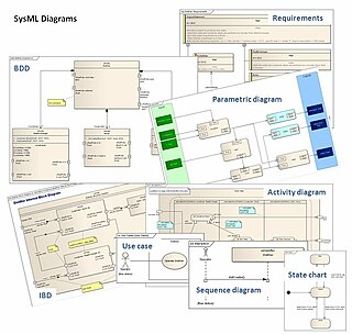
The systems modeling language (SysML) is a general-purpose modeling language for systems engineering applications. It supports the specification, analysis, design, verification and validation of a broad range of systems and systems-of-systems.
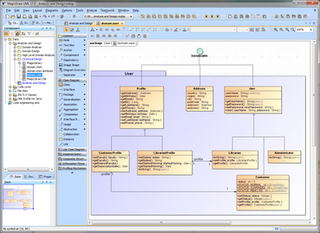
MagicDraw is a proprietary visual UML, SysML, BPMN, and UPDM modeling tool with team collaboration support.
ICONIX is a software development methodology which predates both the Rational Unified Process (RUP), Extreme Programming (XP) and Agile software development. Like RUP, the ICONIX process is UML Use Case driven but more lightweight than RUP. ICONIX provides more requirement and design documentation than XP, and aims to avoid analysis paralysis. The ICONIX Process uses only four UML based diagrams in a four-step process that turns use case text into working code.
The Toolkit for Conceptual Modeling (TCM) is a collection of software tools to present specifications of software systems in the form of diagrams, tables, trees, and the like. TCM offers editors for techniques used in Structured Analysis as well as editors for object-oriented (UML) techniques. For some of the behavior specification techniques, an interface to model checkers is offered. More in particular, TCM contains the following editors.

Misuse case is a business process modeling tool used in the software development industry. The term Misuse Case or mis-use case is derived from and is the inverse of use case. The term was first used in the 1990s by Guttorm Sindre of the Norwegian University of Science and Technology, and Andreas L. Opdahl of the University of Bergen, Norway. It describes the process of executing a malicious act against a system, while use case can be used to describe any action taken by the system.
Process map is a global-system process model that is used to outline the processes that make up the business system and how they interact with each other. Process map shows the processes as objects, which means it is a static and non-algorithmic view of the processes. It should be differentiated from a detailed process model, which shows a dynamic and algorithmic view of the processes, usually known as a process flow diagram. There are different notation standards that can be used for modelling process maps, but the most notable ones are TOGAF Event Diagram, Eriksson-Penker notation, and ARIS Value Added Chain.
UML is a modeling language used by software developers. UML can be used to develop diagrams and provide users (programmers) with ready-to-use, expressive modeling examples. Some UML tools generate program language code from UML. UML can be used for modeling a system independent of a platform language. UML is a graphical language for visualizing, specifying, constructing, and documenting information about software-intensive systems. UML gives a standard way to write a system model, covering conceptual ideas. With an understanding of modeling, the use and application of UML can make the software development process more efficient.
The entity-control-boundary (ECB), or entity-boundary-control (EBC), or boundary-control-entity (BCE) is an architectural pattern used in use-case driven object-oriented programming that structures the classes composing high-level object-oriented source code according to their responsibilities in the use-case realization.