Sequence diagram

Last updated
The Sequence diagram of UML CheckEmail.svg
The Sequence diagram of UML
Overview SsdExample.jpg
Overview

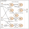
In software engineering, a sequence diagram or system sequence diagram (SSD) shows process interactions arranged in a time sequence. The diagram depicts the processes and objects involved and the sequence of messages exchanged as needed to carry out the functionality. Sequence diagrams are typically associated with use case realizations in the 4+1 architectural view model of the system under development. Sequence diagrams are sometimes called event diagrams or event scenarios.

Contents

For a particular scenario of a use case, the diagrams show the events that external actors generate, their order, and possible inter-system events. [1] All systems are treated as a black box; the diagram places emphasis on events that cross the system boundary from actors to systems. A system sequence diagram should be done for the main success scenario of the use case, and frequent or complex alternative scenarios.

Key elements of sequence diagram

A sequence diagram shows, as parallel vertical lines (lifelines), different processes or objects that live simultaneously, and, as horizontal arrows, the messages exchanged between them, in the order in which they occur. This allows the specification of simple runtime scenarios in a graphical manner.

A system sequence diagram should specify and show the following:

Reading a system sequence diagram

Professionals, in developing a project, often use system sequence diagrams to illustrate how certain tasks are done between users and the system. These tasks may include repetitive, simple, or complex tasks. The purpose is to illustrate the use case in a visual format. In order to construct a system sequence diagram, you need to be familiar with the unified modeling language (UML). These models show the logic behind the actors (people who affect the system) and the system in performing the task. Reading a sequence diagram begins at the top with the actor(s) or the system(s) (which is located at the top of the page). Under each actor or system there are long dotted lines called lifelines, which are attached to them. Actions are performed with lines that extend between these lifelines. When an action line is connected to a lifeline it shows the interaction between the actor or system. Messages will often appear at the top or bottom of a system sequence diagram to illustrate the action in detail. For example, the actor could request to log in, this would be represented by login (username, password). After each action is performed, the response or next action is located under the previous one. As you read down the lines you will see in detail how certain actions are performed in the provided model, and in what order.

Diagram building blocks

If the lifeline is that of an object, it demonstrates a role. Leaving the instance name blank can represent anonymous and unnamed instances. → Messages, written with horizontal arrows with the message name written above them, display interaction. Solid arrow heads represent synchronous calls, open arrow heads represent asynchronous messages, and dashed lines represent reply messages. [2] If a caller sends a synchronous message, it must wait until the message is done, such as invoking a subroutine. If a caller sends an asynchronous message, it can continue processing and doesn’t have to wait for a response. Asynchronous calls are present in multithreaded applications, event-driven applications and in message-oriented middleware. Activation boxes, or method-call boxes, are opaque rectangles drawn on top of lifelines to represent that processes are being performed in response to the message (ExecutionSpecifications in UML).

Objects calling methods on themselves use messages and add new activation boxes on top of any others to indicate a further level of processing. If an object is destroyed (removed from memory), an X is drawn on bottom of the lifeline, and the dashed line ceases to be drawn below it. It should be the result of a message, either from the object itself, or another.

A message sent from outside the diagram can be represented by a message originating from a filled-in circle (found message in UML) or from a border of the sequence diagram (gate in UML).

UML has introduced significant improvements to the capabilities of sequence diagrams. Most of these improvements are based on the idea of interaction fragments [3] which represent smaller pieces of an enclosing interaction. Multiple interaction fragments are combined to create a variety of combined fragments, [4] which are then used to model interactions that include parallelism, conditional branches, optional interactions.

See also

Related Research Articles

<span class="mw-page-title-main">Unified Modeling Language</span> Software system design modeling tool

The unified modeling language (UML) is a general-purpose visual modeling language that is intended to provide a standard way to visualize the design of a system.

In software and systems engineering, the phrase use case is a polyseme with two senses:

  1. A usage scenario for a piece of software; often used in the plural to suggest situations where a piece of software may be useful.
  2. A potential scenario in which a system receives an external request and responds to it.
<span class="mw-page-title-main">Actor (UML)</span>

An actor in the Unified Modeling Language (UML) "specifies a role played by a user or any other system that interacts with the subject."

A stereotype is one of three types of extensibility mechanisms in the Unified Modeling Language (UML), the other two being tags and constraints. They allow designers to extend the vocabulary of UML in order to create new model elements, derived from existing ones, but that have specific properties that are suitable for a particular domain or otherwise specialized usage. The nomenclature is derived from the original meaning of stereotype, used in printing. For example, when modeling a network you might need to have symbols for representing routers and hubs. By using stereotyped nodes you can make these things appear as primitive building blocks.

<span class="mw-page-title-main">Class diagram</span> Type of static structure diagram

In software engineering, a class diagram in the Unified Modeling Language (UML) is a type of static structure diagram that describes the structure of a system by showing the system's classes, their attributes, operations, and the relationships among objects.

<span class="mw-page-title-main">Business Process Model and Notation</span> Graphical representation for specifying business processes

Business Process Model and Notation (BPMN) is a graphical representation for specifying business processes in a business process model.

<span class="mw-page-title-main">Package diagram</span>

A package diagram in the Unified Modeling Language depicts the dependencies between the packages that make up a model.

<span class="mw-page-title-main">Activity diagram</span> Graphical representation of a workflow

Activity diagrams are graphical representations of workflows of stepwise activities and actions with support for choice, iteration and concurrency. In the Unified Modeling Language, activity diagrams are intended to model both computational and organizational processes, as well as the data flows intersecting with the related activities. Although activity diagrams primarily show the overall flow of control, they can also include elements showing the flow of data between activities through one or more data stores.

A timing diagram in the Unified Modeling Language 2.0 is a specific type of interaction diagram, where the focus is on timing constraints.

Glossary of Unified Modeling Language (UML) terms provides a compilation of terminology used in all versions of UML, along with their definitions. Any notable distinctions that may exist between versions are noted with the individual entry it applies to.

<span class="mw-page-title-main">Systems modeling language</span> General-purpose modeling language

The systems modeling language (SysML) is a general-purpose modeling language for systems engineering applications. It supports the specification, analysis, design, verification and validation of a broad range of systems and systems-of-systems.

<span class="mw-page-title-main">Message sequence chart</span> Interaction diagram from the SDL family

A message sequence chart is an interaction diagram from the SDL family standardized by the International Telecommunication Union.

Object-oriented design (OOD) is the process of planning a system of interacting objects for the purpose of solving a software problem. It is a method for software design. By defining classes and their functionality for their children, each object can run the same implementation of the class with its own state.

Composite structure diagram in the Unified Modeling Language (UML) is a type of static structure diagram, that shows the internal structure of a class and the collaborations that this structure makes possible.

In the Unified Modeling Language (UML), a Dependency is a relationship that shows that an element, or set of elements, requires other model elements for their specification or implementation. The element is dependent upon the independent element, called the supplier. Two or more elements in this relationship are called tuples.

In the Unified Modeling Language, an action is a named element that is the fundamental unit of executable functionality. Actions take a set of inputs, which may be empty, and convert them to a set of outputs, which in turn may also be empty.

The first version of the Enterprise Collaboration Architecture (ECA) has been published by the Object Management Group (OMG) in 2001. The vision of the (ECA) is to simplify the development of component based and services oriented systems by providing a modeling framework aligned with the model-driven architecture (MDA) of the Object Management Group (OMG).

<span class="mw-page-title-main">Component (UML)</span>

A component in the Unified Modeling Language represents a modular part of a system that encapsulates the state and behavior of a number of classifiers. Its behavior is defined in terms of provided and required interfaces, is self-contained, and substitutable. A number of UML standard stereotypes exist that apply to components.

<span class="mw-page-title-main">Artifact (UML)</span>

An artifact in the Unified Modeling Language (UML) is the specification of a physical piece of information that is used or produced by a software development process, or by deployment and operation of a system."

UML state machine, also known as UML statechart, is an extension of the mathematical concept of a finite automaton in computer science applications as expressed in the Unified Modeling Language (UML) notation.

References

  1. System Sequence Diagrams
  2. OMG (2011). OMG Unified Modeling Language (OMG UML), Superstructure, V2.4.1, p. 507.
  3. OMG (2008). OMG Unified Modeling Language (OMG UML), Superstructure, V2.1.2, p. 485.
  4. OMG (2007). OMG Unified Modeling Language (OMG UML), Superstructure, V2.1.2. p. 467.