The Unified Modeling Language (UML) is a general-purpose, developmental, modeling language in the field of software engineering that is intended to provide a standard way to visualize the design of a system.
In software engineering, the mediator pattern defines an object that encapsulates how a set of objects interact. This pattern is considered to be a behavioral pattern due to the way it can alter the program's running behavior.
Protocol is a term used by particular object-oriented programming languages with a variety of specific meanings, which other languages may term interface or trait.
In software and systems engineering, a use case is a list of actions or event steps typically defining the interactions between a role and a system to achieve a goal. The actor can be a human or other external system. In systems engineering, use cases are used at a higher level than within software engineering, often representing missions or stakeholder goals. The detailed requirements may then be captured in the Systems Modeling Language (SysML) or as contractual statements.
Astah, formerly known as JUDE, is a UML modeling tool created by Japanese company Change Vision. JUDE received the "Software Product Of The Year 2006" prize, established by Information-Technology Promotion Agency in Japan.
A functional software architecture (FSA) is an architectural model that identifies enterprise functions, interactions and corresponding IT needs. These functions can be used as a reference by different domain experts to develop IT-systems as part of a co-operative information-driven enterprise. In this way, both software engineers and enterprise architects can create an information-driven, integrated organizational environment.

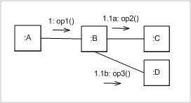
A sequence diagram shows object interactions arranged in time sequence. It depicts the objects and classes involved in the scenario and the sequence of messages exchanged between the objects needed to carry out the functionality of the scenario. Sequence diagrams are typically associated with use case realizations in the Logical View of the system under development. Sequence diagrams are sometimes called event diagrams or event scenarios.

In software engineering, a class diagram in the Unified Modeling Language (UML) is a type of static structure diagram that describes the structure of a system by showing the system's classes, their attributes, operations, and the relationships among objects.
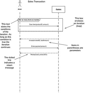
In software engineering, a system sequence diagram (SSD) is a sequence diagram that shows, for a particular scenario of a use case, the events that external actors generate, their order, and possible inter-system events.

Business Process Model and Notation (BPMN) is a graphical representation for specifying business processes in a business process model.
A timing diagram in the Unified Modeling Language 2.0 is a specific type of interaction diagram, where the focus is on timing constraints.
This glossary of Unified Modeling Language terms covers all versions of UML. Individual entries will point out any distinctions that exist between versions.
Executable UML is both a software development method and a highly abstract software language. It was described for the first time in 2002 in the book "Executable UML: A Foundation for Model-Driven Architecture". The language "combines a subset of the UML graphical notation with executable semantics and timing rules." The Executable UML method is the successor to the Shlaer–Mellor method.
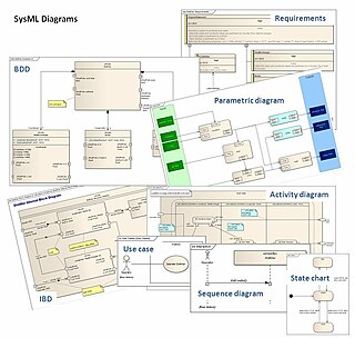
The Systems Modeling Language (SysML) is a general-purpose modeling language for systems engineering applications. It supports the specification, analysis, design, verification and validation of a broad range of systems and systems-of-systems.

A message sequence chart is an interaction diagram from the SDL family standardized by the International Telecommunication Union.
Object-oriented design is the process of planning a system of interacting objects for the purpose of solving a software problem. It is one approach to software design.

An object diagram in the Unified Modeling Language (UML), is a diagram that shows a complete or partial view of the structure of a modeled system at a specific time.

Visual Paradigm (VP-UML) is a UML CASE Tool supporting UML 2, SysML and Business Process Modeling Notation (BPMN) from the Object Management Group (OMG). In addition to modeling support, it provides report generation and code engineering capabilities including code generation. It can reverse engineer diagrams from code, and provide round-trip engineering for various programming languages.
Enterprise engineering is defined as the body of knowledge, principles, and practices to design all or part of an enterprise. An enterprise is a complex, socio-technical system that comprises interdependent resources of people, information, and technology that must interact with each other and their environment in support of a common mission. According to Kosanke, Vernadat and Zelm, enterprise engineering is an enterprise life-cycle oriented discipline for the identification, design, and implementation of enterprises and their continuous evolution, supported by enterprise modelling. The discipline examines each aspect of the enterprise, including business processes, information flows, material flows, and organizational structure. Enterprise engineering may focus on the design of the enterprise as a whole, or on the design and integration of certain business components.
UML is a modeling language used by software developers. UML can be used to develop diagrams and provide users (programmers) with ready-to-use, expressive modeling examples. Some UML tools generate program language code from UML. UML can be used for modeling a system independent of a platform language. UML is a graphical language for visualizing, specifying, constructing, and documenting information about software-intensive systems. UML gives a standard way to write a system model, covering conceptual ideas. With an understanding of modeling, the use and application of UML can make the software development process more efficient.