Activity diagrams[1] are graphical representations of workflows of stepwise activities and actions[2] with support for choice, iteration, and concurrency. In the Unified Modeling Language, activity diagrams are intended to model both computational and organizational processes (i.e., workflows), as well as the data flows intersecting with the related activities.[1][3] "Object nodes hold data that is input to and output from executable nodes, and moves across object flow edges. Control nodes specify sequencing of executable nodes via control flow edges."[1] In other words, although activity diagrams primarily show the overall control flow, they can also include elements showing the data flow between activities through one or more data stores.[1]
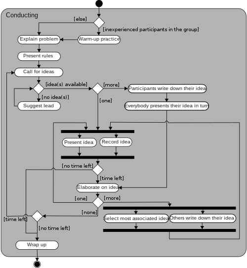
bars represent the start (split) or end (join) of concurrent activities;
a black circle represents the start (initial node) of the workflow;
an encircled black circle represents the end (final node).
Arrows run from the start towards the end and represent the order in which activities happen.
Activity diagrams can be regarded as a form of a structured flowchart combined with a traditional data flow diagram. Typical flowchart techniques lack constructs for expressing concurrency.[5] However, the join and split symbols in activity diagrams only resolve this for simple cases. The meaning of the model is not clear when these symbols are arbitrarily combined with decisions or loops.[citation needed]
While in UML 1.x, activity diagrams were a specialized form of state diagram,[6] in UML 2.x, the activity diagrams were reformalized to be based on Petri net-like semantics, increasing the scope of situations that can be modeled using activity diagrams.[7] These changes cause many UML 1.x activity diagrams to be interpreted differently in UML 2.x.[citation needed]
UML activity diagrams in version 2.x can be used in various domains, e.g. in design of embedded systems. It is possible to verify such a specification using model checking techniques.[8]
↑ Dumas, Marlon, and Arthur H.M. Ter Hofstede. "UML activity diagrams as a workflow specification language." ≪ UML≫ 2001—The Unified Modeling Language. Modeling Languages, Concepts, and Tools. Springer Berlin Heidelberg, 2001. 76-90.
↑ Störrle, Harald, and J. H. Hausmann. "semantics of uml 2.0 activities." Proceedings of the IEEE Symposium on Visual Languages and Human-Centric Computing. 2004.
↑ I. Grobelna, M. Grobelny, M. Adamski, "Model Checking of UML Activity Diagrams in Logic Controllers Design", Proceedings of the Ninth International Conference on Dependability and Complex Systems DepCoS-RELCOMEX, Advances in Intelligent Systems and Computing Volume 286, Springer International Publishing Switzerland, pp. 233-242, 2014
This page is based on this Wikipedia article Text is available under the CC BY-SA 4.0 license; additional terms may apply. Images, videos and audio are available under their respective licenses.