
In object-oriented programming, an object diagram [1] in the Unified Modeling Language (UML) is a diagram that shows a complete or partial view of the structure of a modeled system at a specific time.
In object-oriented programming, an object diagram [1] in the Unified Modeling Language (UML) is a diagram that shows a complete or partial view of the structure of a modeled system at a specific time.
| UML diagram types |
|---|
| Structural UML diagrams |
| Behavioral UML diagrams |
In the Unified Modeling Language (UML), an object diagram focuses on some particular set of objects and attributes, and the links between these instances. A correlated set of object diagrams provides insight into how an arbitrary view of a system is expected to evolve over time. Early UML specifications described object diagrams as such: [2] [3]
"An object diagram is a graph of instances, including objects and data values. A static object diagram is an instance of a class diagram; it shows a snapshot of the detailed state of a system at a point in time. The use of object diagrams is fairly limited, namely to show examples of data structure."
The latest UML 2.5.1 specification does not explicitly define object diagrams, [4] but provides a notation for "instances" of classifiers. [4] : 126
Object diagrams and class diagrams are closely related [5] and use almost identical notation. [6] Both diagrams are meant to visualize static structure of a system. While class diagrams show classes, object diagrams display instances of classes (objects). [7] Object diagrams are more concrete than class diagrams. They are often used to provide examples or act as test cases for class diagrams. Only aspects of current interest in a model are typically shown on an object diagram.
Each object and link on an object diagram is represented by an InstanceSpecification. This can show an object's classifier (e.g. an abstract or concrete class) and instance name, as well as attributes and other structural features using slots. Each slot corresponds to a single attribute or feature, and may include a value for that entity.
The name on an instance specification optionally shows an instance name, a ':' separator, and optionally one or more classifier names separated by commas. The contents of slots, if any, are included below the names, in a separate attribute compartment. A link is shown as a solid line, and represents an instance of an association.

Consider one possible way of modeling production of the Fibonacci sequence.
In the first UML object diagram on the right, the instance in the leftmost instance specification is named v1, has IndependentVariable as its classifier, plays the NMinus2 role within the FibonacciSystem, and has a slot for the val attribute with a value of 0. The second object is named v2, is of class IndependentVariable, plays the NMinus1 role, and has val = 1. The DependentVariable object is named v3, and plays the N role. The topmost instance, an anonymous instance specification, has FibonacciFunction as its classifier, and may have an instance name, a role, and slots, but these are not shown here. The diagram also includes three named links, shown as lines. Links are instances of an association.

In the second diagram, at a slightly later point in time, the IndependentVariable and DependentVariable objects are the same, but the slots for the val attribute have different values. The role names are not shown here.

In the last object diagram, a still later snapshot, the same three objects are involved. Their slots have different values. The instance and role names are not shown here.
If you are using a UML modeling tool, you will typically draw object diagrams using some other diagram type, such as on a class diagram. An object instance may be called an instance specification or just an instance. A link between instances is generally referred to as a link. Other UML entities, such as an aggregation or composition symbol (a diamond) may also appear on an object diagram.
An object-modeling language is a standardized set of symbols used to model a software system using an object-oriented framework. The symbols can be either informal or formal ranging from predefined graphical templates to formal object models defined by grammars and specifications.
The unified modeling language (UML) is a general-purpose visual modeling language that is intended to provide a standard way to visualize the design of a system.
An actor in the Unified Modeling Language (UML) "specifies a role played by a user or any other system that interacts with the subject."
A stereotype is one of three types of extensibility mechanisms in the Unified Modeling Language (UML), the other two being tags and constraints. They allow designers to extend the vocabulary of UML in order to create new model elements, derived from existing ones, but that have specific properties that are suitable for a particular domain or otherwise specialized usage. The nomenclature is derived from the original meaning of stereotype, used in printing. For example, when modeling a network you might need to have symbols for representing routers and hubs. By using stereotyped nodes you can make these things appear as primitive building blocks.

In software engineering, a sequence diagram shows process interactions arranged in time sequence. This diagram depicts the processes and objects involved and the sequence of messages exchanged as needed to carry out the functionality. Sequence diagrams are typically associated with use case realizations in the 4+1 architectural view model of the system under development. Sequence diagrams are sometimes called event diagrams or event scenarios.

In software engineering, a class diagram in the Unified Modeling Language (UML) is a type of static structure diagram that describes the structure of a system by showing the system's classes, their attributes, operations, and the relationships among objects.

A package diagram in the Unified Modeling Language depicts "specializations for Models and for Profiles that organize extensions to UML."
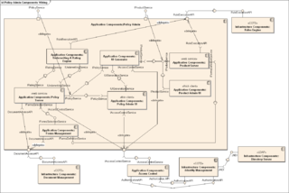
In Unified Modeling Language (UML), a component diagram depicts how components are wired together to form larger components or software systems. They are used to illustrate the structure of arbitrarily complex systems.

Activity diagrams are graphical representations of workflows of stepwise activities and actions with support for choice, iteration, and concurrency. In the Unified Modeling Language, activity diagrams are intended to model both computational and organizational processes, as well as the data flows intersecting with the related activities. "Object nodes hold data that is input to and output from executable nodes, and moves across object flow edges. Control nodes specify sequencing of executable nodes via control flow edges." In other words, although activity diagrams primarily show the overall control flow, they can also include elements showing the data flow between activities through one or more data stores.

A communication diagram in Unified Modeling Language (UML) 2.5.1 is a simplified version of the UML 1.x collaboration diagram.
Glossary of Unified Modeling Language (UML) terms provides a compilation of terminology used in all versions of UML, along with their definitions. Any notable distinctions that may exist between versions are noted with the individual entry it applies to.
Executable UML is both a software development method and a highly abstract software language. It was described for the first time in 2002 in the book "Executable UML: A Foundation for Model-Driven Architecture". The language "combines a subset of the UML graphical notation with executable semantics and timing rules." The Executable UML method is the successor to the Shlaer–Mellor method.
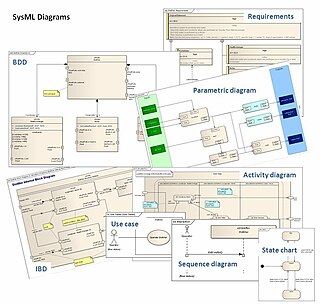
The systems modeling language (SysML) is a general-purpose modeling language for systems engineering applications. It supports the specification, analysis, design, verification and validation of a broad range of systems and systems-of-systems.
Composite structure diagram in the Unified Modeling Language (UML) is a type of static structure diagram that shows the internal structure of a class and the collaborations that this structure makes possible.
In the Unified Modeling Language 1.x, powertype is a keyword for a specific UML stereotype, and applies to a class or dependency. Powertype shows a classifier whose instances (objects) are children of the given parent.
In the Unified Modeling Language (UML), a Dependency is "a Relationship that signifies that a single model Element or a set of model Elements requires other model Elements for their specification or implementation." "This means that the complete semantics of the client Element(s) are either semantically or structurally dependent on the definition of the supplier Element(s)." Two or more elements in this relationship are called tuples.

A component in the Unified Modeling Language represents a modular part of a system that encapsulates the state and behavior of a number of classifiers. Its behavior is defined in terms of provided and required interfaces, is self-contained, and substitutable. A number of UML standard stereotypes exist that apply to components.
UML state machine, formerly known as UML statechart, is an extension of the mathematical concept of a finite automaton in computer science applications as expressed in the Unified Modeling Language (UML) notation.

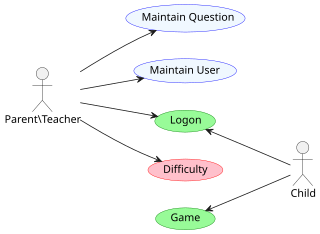
A use case diagram is a graphical depiction of a user's possible interactions with a system. A use case diagram shows various use cases and different types of users the system has and will often be accompanied by other types of diagrams as well. The use cases are represented by either circles or ellipses. The actors are often shown as stick figures.
In Unified Modeling Language (UML) 2.5.1, an Element is "a constituent of a model. As such, it has the capability of owning other Elements."
| Actors |
|  | |||||||||||
|---|---|---|---|---|---|---|---|---|---|---|---|---|---|
| Concepts |
| ||||||||||||
| Diagrams |
| ||||||||||||
| Derived languages | |||||||||||||
| Other topics | |||||||||||||