Interaction overview diagram

Last updated
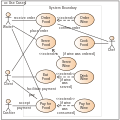
Interaction overview diagram Uml-Iod-Diagram1.svg
Interaction overview diagram

Interaction Overview Diagram [1] is one of the fourteen "nominative" types of diagrams [2] of the Unified Modeling Language (UML), which can picture a control flow with nodes that can contain interaction diagrams.

The interaction overview diagram is similar to the activity diagram, in that both visualize a sequence of activities. The difference is that, for an interaction overview, each individual activity is pictured as a frame which can contain a nested interaction diagram. This makes the interaction overview diagram useful to "deconstruct a complex scenario that would otherwise require multiple if-then-else paths to be illustrated as a single sequence diagram". [3]

The other notation elements for interaction overview diagrams are the same as for activity diagrams. These include initial, final, decision, merge, fork and join nodes. The two new elements in the interaction overview diagrams are the "interaction occurrences" and "interaction elements." [4]
Related Research Articles

<span class="mw-page-title-main">Object-modeling language</span> Component in software development

An object-modeling language is a standardized set of symbols used to model a software system using an object-oriented framework. The symbols can be either informal or formal ranging from predefined graphical templates to formal object models defined by grammars and specifications.

<span class="mw-page-title-main">Unified Modeling Language</span> Software system design modeling tool

The unified modeling language (UML) is a general-purpose visual modeling language that is intended to provide a standard way to visualize the design of a system.

The XML Metadata Interchange (XMI) is an Object Management Group (OMG) standard for exchanging metadata information via Extensible Markup Language (XML).

<span class="mw-page-title-main">Business process modeling</span> Activity of representing processes of an enterprise

Business process modeling (BPM), mainly used in business process management; software development, or systems engineering, is the action of capturing and representing processes of an enterprise, so that the current business processes may be analyzed, applied securely and consistently, improved, and automated. BPM is typically orchestrated by business analysts, leveraging their expertise in modeling practices. Subject matter experts, equipped with specialized knowledge of the processes being modeled, often collaborate within these teams. Alternatively, process models can be directly derived from digital traces within IT systems, such as event logs, utilizing process mining tools.

A stereotype is one of three types of extensibility mechanisms in the Unified Modeling Language (UML), the other two being tags and constraints. They allow designers to extend the vocabulary of UML in order to create new model elements, derived from existing ones, but that have specific properties that are suitable for a particular domain or otherwise specialized usage. The nomenclature is derived from the original meaning of stereotype, used in printing. For example, when modeling a network you might need to have symbols for representing routers and hubs. By using stereotyped nodes you can make these things appear as primitive building blocks.

<span class="mw-page-title-main">Sequence diagram</span> Visualisation of computer system processes

In software engineering, a sequence diagram shows process interactions arranged in time sequence. This diagram depicts the processes and objects involved and the sequence of messages exchanged as needed to carry out the functionality. Sequence diagrams are typically associated with use case realizations in the 4+1 architectural view model of the system under development. Sequence diagrams are sometimes called event diagrams or event scenarios.

<span class="mw-page-title-main">Business Process Model and Notation</span> Graphical representation for specifying business processes

Business Process Model and Notation (BPMN) is a graphical representation for specifying business processes in a business process model.

<span class="mw-page-title-main">StarUML</span> UML diagram software

StarUML is a software engineering tool for system modeling using the Unified Modeling Language, as well as Systems Modeling Language, and classical modeling notations. It is published by MKLabs and is available on Windows, Linux and MacOS.

<span class="mw-page-title-main">Package diagram</span>

A package diagram in the Unified Modeling Language depicts the dependencies between the packages that make up a model.

<span class="mw-page-title-main">Component diagram</span> Diagram depicting how components are wired together to form software systems

In Unified Modeling Language (UML), a component diagram depicts how components are wired together to form larger components or software systems. They are used to illustrate the structure of arbitrarily complex systems.

<span class="mw-page-title-main">Activity diagram</span> Graphical representation of a workflow

Activity diagrams are graphical representations of workflows of stepwise activities and actions with support for choice, iteration, and concurrency. In the Unified Modeling Language, activity diagrams are intended to model both computational and organizational processes, as well as the data flows intersecting with the related activities. "Object nodes hold data that is input to and output from executable nodes, and moves across object flow edges. Control nodes specify sequencing of executable nodes via control flow edges." In other words, although activity diagrams primarily show the overall control flow, they can also include elements showing the data flow between activities through one or more data stores.

<span class="mw-page-title-main">Communication diagram</span>

A communication diagram in Unified Modeling Language (UML) 2.5.1 is a simplified version of the UML 1.x collaboration diagram.

A timing diagram in Unified Modeling Language 2.5.1 is a specific type of interaction diagram, where the focus is on timing constraints.

Glossary of Unified Modeling Language (UML) terms provides a compilation of terminology used in all versions of UML, along with their definitions. Any notable distinctions that may exist between versions are noted with the individual entry it applies to.

<span class="mw-page-title-main">Systems modeling language</span> General-purpose modeling language

The systems modeling language (SysML) is a general-purpose modeling language for systems engineering applications. It supports the specification, analysis, design, verification and validation of a broad range of systems and systems-of-systems.

<span class="mw-page-title-main">MagicDraw</span> Systems modelling software

MagicDraw is a proprietary visual UML, SysML, BPMN, and UPDM modeling tool with team collaboration support.

<span class="mw-page-title-main">Object diagram</span> Diagram showing the structure of objects in a system

In object-oriented programming, an object diagram in the Unified Modeling Language (UML) is a diagram that shows a complete or partial view of the structure of a modeled system at a specific time.

The Business Process Definition Metamodel (BPDM) is a standard definition of concepts used to express business process models, adopted by the OMG. Metamodels define concepts, relationships, and semantics for exchange of user models between different modeling tools. The exchange format is defined by XSD and XMI, a specification for transformation of OMG metamodels to XML. Pursuant to the OMG's policies, the metamodel is the result of an open process involving submissions by member organizations, following a Request for Proposal (RFP) issued in 2003. BPDM was adopted in initial form in July 2007, and finalized in July 2008.

UML is a modeling language used by software developers. UML can be used to develop diagrams and provide users (programmers) with ready-to-use, expressive modeling examples. Some UML tools generate program language code from UML. UML can be used for modeling a system independent of a platform language. UML is a graphical language for visualizing, specifying, constructing, and documenting information about software-intensive systems. UML gives a standard way to write a system model, covering conceptual ideas. With an understanding of modeling, the use and application of UML can make the software development process more efficient.

<span class="mw-page-title-main">Interaction Flow Modeling Language</span>

The Interaction Flow Modeling Language (IFML) is a standardized modeling language in the field of software engineering. IFML includes a set of graphic notations to create visual models of user interactions and front-end behavior in software systems.

References

  1. "Interaction Overview Diagram". Unified Modeling Language 2.5.1. OMG Document Number formal/2017-12-05. Object Management Group Standards Development Organization (OMG SDO). December 2017. p. 601.
  2. "Annex A: Diagrams (normative)". Unified Modeling Language 2.5.1. OMG Document Number formal/2017-12-05. Object Management Group Standards Development Organization (OMG SDO). December 2017. p. 683.
  3. UModel Interaction Overview Diagrams. Retrieved 12 Sept 2008.
  4. Sparx Systems - UML 2 Tutorial - Interaction Overview Diagram. Retrieved 12 Sept 2008.