In software engineering, multitier architecture is a client–server architecture in which presentation, application processing and data management functions are physically separated. The most widespread use of multitier architecture is the three-tier architecture.

The unified modeling language (UML) is a general-purpose visual modeling language that is intended to provide a standard way to visualize the design of a system.
In software quality assurance, performance testing is in general a testing practice performed to determine how a system performs in terms of responsiveness and stability under a particular workload. It can also serve to investigate, measure, validate or verify other quality attributes of the system, such as scalability, reliability and resource usage.
Model-driven architecture (MDA) is a software design approach for the development of software systems. It provides a set of guidelines for the structuring of specifications, which are expressed as models. Model Driven Architecture is a kind of domain engineering, and supports model-driven engineering of software systems. It was launched by the Object Management Group (OMG) in 2001.
An application program is a computer program designed to carry out a specific task other than one relating to the operation of the computer itself, typically to be used by end-users. Word processors, media players, and accounting software are examples. The collective noun "application software" refers to all applications collectively. The other principal classifications of software are system software, relating to the operation of the computer, and utility software ("utilities").
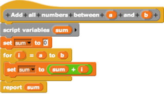
In computing, a visual programming language, also known as diagrammatic programming, graphical programming or block coding, is a programming language that lets users create programs by manipulating program elements graphically rather than by specifying them textually. A VPL allows programming with visual expressions, spatial arrangements of text and graphic symbols, used either as elements of syntax or secondary notation. For example, many VPLs are based on the idea of "boxes and arrows", where boxes or other screen objects are treated as entities, connected by arrows, lines or arcs which represent relations. VPLs are generally the basis of Low-code development platforms.

Model-based testing is an application of model-based design for designing and optionally also executing artifacts to perform software testing or system testing. Models can be used to represent the desired behavior of a system under test (SUT), or to represent testing strategies and a test environment. The picture on the right depicts the former approach.
A stereotype is one of three types of extensibility mechanisms in the Unified Modeling Language (UML), the other two being tags and constraints. They allow designers to extend the vocabulary of UML in order to create new model elements, derived from existing ones, but that have specific properties that are suitable for a particular domain or otherwise specialized usage. The nomenclature is derived from the original meaning of stereotype, used in printing. For example, when modeling a network you might need to have symbols for representing routers and hubs. By using stereotyped nodes you can make these things appear as primitive building blocks.
Software deployment is all of the activities that make a software system available for use.

In software engineering, a class diagram in the Unified Modeling Language (UML) is a type of static structure diagram that describes the structure of a system by showing the system's classes, their attributes, operations, and the relationships among objects.

Business Process Model and Notation (BPMN) is a graphical representation for specifying business processes in a business process model.

Activity diagrams are graphical representations of workflows of stepwise activities and actions with support for choice, iteration, and concurrency. In the Unified Modeling Language, activity diagrams are intended to model both computational and organizational processes, as well as the data flows intersecting with the related activities. "Object nodes hold data that is input to and output from executable nodes, and moves across object flow edges. Control nodes specify sequencing of executable nodes via control flow edges." In other words, although activity diagrams primarily show the overall control flow, they can also include elements showing the data flow between activities through one or more data stores.
Glossary of Unified Modeling Language (UML) terms provides a compilation of terminology used in all versions of UML, along with their definitions. Any notable distinctions that may exist between versions are noted with the individual entry it applies to.
Executable UML is both a software development method and a highly abstract software language. It was described for the first time in 2002 in the book "Executable UML: A Foundation for Model-Driven Architecture". The language "combines a subset of the UML graphical notation with executable semantics and timing rules." The Executable UML method is the successor to the Shlaer–Mellor method.
In computing, virtualization (v12n) is a series of technologies that allows dividing of physical computing resources into a series of virtual machines, operating systems, processes or containers.

A computer cluster is a set of computers that work together so that they can be viewed as a single system. Unlike grid computers, computer clusters have each node set to perform the same task, controlled and scheduled by software. The newest manifestation of cluster computing is cloud computing.
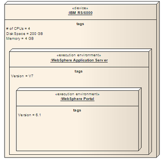
A node in the Unified Modeling Language (UML) is a computational resource upon which UML artifacts may be deployed for execution.
UML is a modeling language used by software developers. UML can be used to develop diagrams and provide users (programmers) with ready-to-use, expressive modeling examples. Some UML tools generate program language code from UML. UML can be used for modeling a system independent of a platform language. UML is a graphical language for visualizing, specifying, constructing, and documenting information about software-intensive systems. UML gives a standard way to write a system model, covering conceptual ideas. With an understanding of modeling, the use and application of UML can make the software development process more efficient.
The Interaction Flow Modeling Language (IFML) is a standardized modeling language in the field of software engineering. IFML includes a set of graphic notations to create visual models of user interactions and front-end behavior in software systems.
This glossary of computer science is a list of definitions of terms and concepts used in computer science, its sub-disciplines, and related fields, including terms relevant to software, data science, and computer programming.

