Booch worked at Vandenberg Air Force Base after he graduated. He started as a project engineer and later managed ground-support missions for the space shuttle and other projects. After he gained his master's degree he became an instructor at the Air Force Academy.[6]
Booch served as Chief Scientist of Rational Software Corporation from its founding in 1981 through its acquisition by IBM in 2003, where he continued to work until March 2008. After this he became Chief Scientist, Software Engineering in IBM Research and series editor for Benjamin Cummings.
Booch has devoted his life's work to improving the art and the science of software development. In the 1980s, he wrote one of the more popular books on programming in Ada. He is best known for developing the Unified Modeling Language with Ivar Jacobson and James Rumbaugh in the 1990s.
IBM 1130
Booch got his first exposure to programming on an IBM 1130.[7]
... I pounded the doors at the local IBM sales office until a salesman took pity on me. After we chatted for a while, he handed me a Fortran [manual]. I'm sure he gave it to me thinking, "I'll never hear from this kid again." I returned the following week saying, "This is really cool. I've read the whole thing and have written a small program. Where can I find a computer?" The fellow, to my delight, found me programming time on an IBM 1130 on weekends and late-evening hours. That was my first programming experience, and I must thank that anonymous IBM salesman for launching my career. Thank you, IBM.
Booch method
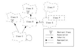
Class diagram
Booch developed the 'Booch method' of software development, which he presents in his 1991/94 book, Object Oriented Analysis and Design With Applications.[8] The method was authored by Booch when he was working for Rational Software (acquired by IBM), published in 1992 and revised in 1994.
The method is composed of an object-oriented modeling language,[9] an iterative object-oriented development process,[10] and a set of recommended practices.[11] The recommended practices include adding more classes to simplify complex code. The methodology was widely used in software engineering for object-oriented analysis and design and benefited from ample documentation and support tools.[12]
The Booch notation is characterized by cloud shapes to represent classes and distinguishes the following diagrams:
Methodological aspects of the Booch method have been incorporated into several methodologies and processes, the primary such methodology being the Rational Unified Process (RUP).
Design patterns
Booch is also an advocate of design patterns. For instance, he wrote the foreword to Design Patterns, an early and highly influential book in the field.
IBM Research – Almaden
He now is part of IBM Research – Almaden, serving as Chief Scientist for Software Engineering, where he continues his work on the "Handbook of Software Architecture" and also leads several long-term projects in software engineering. Grady has served as architect and architectural mentor for numerous complex software-intensive systems around the world.
Publications
Grady Booch published several articles and books. A selection:
This page is based on this Wikipedia article Text is available under the CC BY-SA 4.0 license; additional terms may apply. Images, videos and audio are available under their respective licenses.