The unified modeling language (UML) is a general-purpose visual modeling language that is intended to provide a standard way to visualize the design of a system.
In software and systems engineering, the phrase use case is a polyseme with two senses:
- A usage scenario for a piece of software; often used in the plural to suggest situations where a piece of software may be useful.
- A potential scenario in which a system receives an external request and responds to it.
The Object Constraint Language (OCL) is a declarative language describing rules applying to Unified Modeling Language (UML) models developed at IBM and is now part of the UML standard. Initially, OCL was merely a formal specification language extension for UML. OCL may now be used with any Meta-Object Facility (MOF) Object Management Group (OMG) meta-model, including UML. The Object Constraint Language is a precise text language that provides constraint and object query expressions on any MOF model or meta-model that cannot otherwise be expressed by diagrammatic notation. OCL is a key component of the new OMG standard recommendation for transforming models, the Queries/Views/Transformations (QVT) specification.
A stereotype is one of three types of extensibility mechanisms in the Unified Modeling Language (UML), the other two being tags and constraints. They allow designers to extend the vocabulary of UML in order to create new model elements, derived from existing ones, but that have specific properties that are suitable for a particular domain or otherwise specialized usage. The nomenclature is derived from the original meaning of stereotype, used in printing. For example, when modeling a network you might need to have symbols for representing routers and hubs. By using stereotyped nodes you can make these things appear as primitive building blocks.

In software engineering, a sequence diagram shows process interactions arranged in time sequence. This diagram depicts the processes and objects involved and the sequence of messages exchanged as needed to carry out the functionality. Sequence diagrams are typically associated with use case realizations in the 4+1 architectural view model of the system under development. Sequence diagrams are sometimes called event diagrams or event scenarios.

In software engineering, a class diagram in the Unified Modeling Language (UML) is a type of static structure diagram that describes the structure of a system by showing the system's classes, their attributes, operations, and the relationships among objects.

A package diagram in the Unified Modeling Language depicts "specializations for Models and for Profiles that organize extensions to UML."
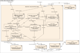
In Unified Modeling Language (UML), a component diagram depicts how components are wired together to form larger components or software systems. They are used to illustrate the structure of arbitrarily complex systems.

Activity diagrams are graphical representations of workflows of stepwise activities and actions with support for choice, iteration, and concurrency. In the Unified Modeling Language, activity diagrams are intended to model both computational and organizational processes, as well as the data flows intersecting with the related activities. "Object nodes hold data that is input to and output from executable nodes, and moves across object flow edges. Control nodes specify sequencing of executable nodes via control flow edges." In other words, although activity diagrams primarily show the overall control flow, they can also include elements showing the data flow between activities through one or more data stores.

A communication diagram in Unified Modeling Language (UML) 2.5.1 is a simplified version of the UML 1.x collaboration diagram.
Glossary of Unified Modeling Language (UML) terms provides a compilation of terminology used in all versions of UML, along with their definitions. Any notable distinctions that may exist between versions are noted with the individual entry it applies to.
Executable UML is both a software development method and a highly abstract software language. It was described for the first time in 2002 in the book "Executable UML: A Foundation for Model-Driven Architecture". The language "combines a subset of the UML graphical notation with executable semantics and timing rules." The Executable UML method is the successor to the Shlaer–Mellor method.

In object-oriented programming, an object diagram in the Unified Modeling Language (UML) is a diagram that shows a complete or partial view of the structure of a modeled system at a specific time.
Composite structure diagram in the Unified Modeling Language (UML) is a type of static structure diagram, that shows the internal structure of a class and the collaborations that this structure makes possible.
In the Unified Modeling Language 1.x, powertype is a keyword for a specific UML stereotype, and applies to a class or dependency. Powertype shows a classifier whose instances (objects) are children of the given parent.
The first version of the Enterprise Collaboration Architecture (ECA) has been published by the Object Management Group (OMG) in 2001. The vision of the (ECA) is to simplify the development of component based and services oriented systems by providing a modeling framework aligned with the model-driven architecture (MDA) of the Object Management Group (OMG).

Interaction Overview Diagram is one of the fourteen "nominative" types of diagrams of the Unified Modeling Language (UML), which can picture a control flow with nodes that can contain interaction diagrams.

An artifact in the Unified Modeling Language (UML) is the specification of a physical piece of information that is used or produced by a software development process, or by deployment and operation of a system."
UML state machine, formerly known as UML statechart, is an extension of the mathematical concept of a finite automaton in computer science applications as expressed in the Unified Modeling Language (UML) notation.

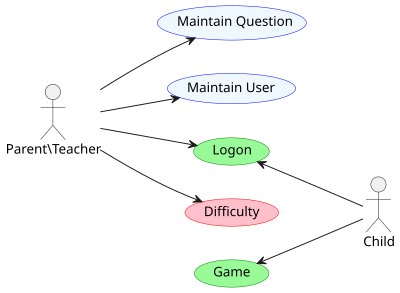
A use case diagram is a graphical depiction of a user's possible interactions with a system. A use case diagram shows various use cases and different types of users the system has and will often be accompanied by other types of diagrams as well. The use cases are represented by either circles or ellipses. The actors are often shown as stick figures.