
The unified modeling language (UML) is a general-purpose visual modeling language that is intended to provide a standard way to visualize the design of a system.
The XML Metadata Interchange (XMI) is an Object Management Group (OMG) standard for exchanging metadata information via Extensible Markup Language (XML).
Model Driven Architecture (MDA) is a software design approach for the development of software systems. It provides a set of guidelines for the structuring of specifications, which are expressed as models. Model Driven Architecture is a kind of domain engineering, and supports model-driven engineering of software systems. It was launched by the Object Management Group (OMG) in 2001.
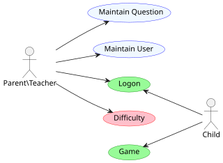
An actor in the Unified Modeling Language (UML) "specifies a role played by a user or any other system that interacts with the subject."
Round-trip engineering (RTE) in the context of model-driven architecture is a functionality of software development tools that synchronizes two or more related software artifacts, such as, source code, models, configuration files, documentation, etc. between each other. The need for round-trip engineering arises when the same information is present in multiple artifacts and when an inconsistency may arise in case some artifacts are updated. For example, some piece of information was added to/changed in only one artifact and, as a result, it became missing in/inconsistent with the other artifacts.

In software engineering, a sequence diagram shows process interactions arranged in time sequence. This diagram depicts the processes and objects involved and the sequence of messages exchanged as needed to carry out the functionality. Sequence diagrams are typically associated with use case realizations in the 4+1 architectural view model of the system under development. Sequence diagrams are sometimes called event diagrams or event scenarios.

StarUML is a software engineering tool for system modeling using the Unified Modeling Language, as well as Systems Modeling Language, and classical modeling notations. It is published by MKLabs and is available on Windows, Linux and MacOS.

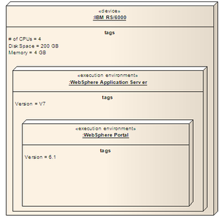
A deployment diagram "specifies constructs that can be used to define the execution architecture of systems and the assignment of software artifacts to system elements." To describe a web site, for example, a deployment diagram would show what hardware components ("nodes") exist, what software components ("artifacts") run on each node, and how the different pieces are connected.

A package diagram in the Unified Modeling Language depicts "specializations for Models and for Profiles that organize extensions to UML."
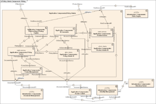
In Unified Modeling Language (UML), a component diagram depicts how components are wired together to form larger components or software systems. They are used to illustrate the structure of arbitrarily complex systems.

Activity diagrams are graphical representations of workflows of stepwise activities and actions with support for choice, iteration, and concurrency. In the Unified Modeling Language, activity diagrams are intended to model both computational and organizational processes, as well as the data flows intersecting with the related activities. "Object nodes hold data that is input to and output from executable nodes, and moves across object flow edges. Control nodes specify sequencing of executable nodes via control flow edges." In other words, although activity diagrams primarily show the overall control flow, they can also include elements showing the data flow between activities through one or more data stores.
UML Partners was a consortium of system integrators and vendors convened in 1996 to specify the Unified Modeling Language (UML). Initially the consortium was led by Grady Booch, Ivar Jacobson, and James Rumbaugh of Rational Software. The UML Partners' UML 1.0 specification draft was proposed to the Object Management Group (OMG) in January 1997. During the same month the UML Partners formed a Semantics Task Force, chaired by Cris Kobryn, to finalize the semantics of the specification and integrate it with other standardization efforts. The result of this work, UML 1.1, was submitted to the OMG in August 1997 and adopted by the OMG in November 1997.
Model-driven engineering (MDE) is a software development methodology that focuses on creating and exploiting domain models, which are conceptual models of all the topics related to a specific problem. Hence, it highlights and aims at abstract representations of the knowledge and activities that govern a particular application domain, rather than the computing concepts.
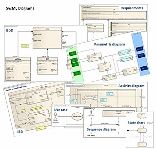
The systems modeling language (SysML) is a general-purpose modeling language for systems engineering applications. It supports the specification, analysis, design, verification and validation of a broad range of systems and systems-of-systems.
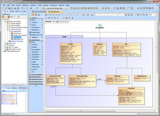
MagicDraw is a proprietary visual UML, SysML, BPMN, and UPDM modeling tool with team collaboration support.
The first version of the Enterprise Collaboration Architecture (ECA) has been published by the Object Management Group (OMG) in 2001. The vision of the (ECA) is to simplify the development of component based and services oriented systems by providing a modeling framework aligned with the model-driven architecture (MDA) of the Object Management Group (OMG).

A component in the Unified Modeling Language represents a modular part of a system that encapsulates the state and behavior of a number of classifiers. Its behavior is defined in terms of provided and required interfaces, is self-contained, and substitutable. A number of UML standard stereotypes exist that apply to components.
A node in the Unified Modeling Language (UML) is a computational resource upon which UML artifacts may be deployed for execution.

In Unified Modeling Language in the field of software engineering, a profile diagram operates at the metamodel level to show stereotypes as classes with the «stereotype» stereotype, and profiles as packages with the «profile» stereotype. The extension relation indicates what metamodel element a given stereotype is extending.

A use case diagram is a graphical depiction of a user's possible interactions with a system. A use case diagram shows various use cases and different types of users the system has and will often be accompanied by other types of diagrams as well. The use cases are represented by either circles or ellipses. The actors are often shown as stick figures.

