State diagram

Last updated

A state diagram for a door that can only be opened and closed Finite state machine example with comments.svg
A state diagram for a door that can only be opened and closed

A state diagram is a type of diagram used in computer science and related fields to describe the behavior of systems. State diagrams require that the system is composed of a finite number of states. Sometimes, this is indeed the case, while at other times this is a reasonable abstraction. Many forms of state diagrams exist, which differ slightly and have different semantics.

Contents

Overview

State diagrams are used to give an abstract description of a system's behavior. This behavior is analyzed and represented by a series of events that can occur in one or more possible states. Hereby "each diagram usually represents objects of a single class and track the different states of its objects through the system". [1]

State diagrams can be used to graphically represent finite-state machines (also called finite automata). This was introduced by Claude Shannon and Warren Weaver in their 1949 book The Mathematical Theory of Communication. Another source is Taylor Booth in his 1967 book Sequential Machines and Automata Theory. Another possible representation is the state-transition table.

Directed graph

A directed graph Directed.svg
A directed graph

A classic form of state diagram for a finite automaton (FA) is a directed graph with the following elements (Q, Σ, Z, δ, q0, F): [2] [3]

The output function ω represents the mapping of ordered pairs of input symbols and states onto output symbols, denoted mathematically as ω : Σ × QZ.

For a deterministic finite automaton (DFA), nondeterministic finite automaton (NFA), generalized nondeterministic finite automaton (GNFA), or Moore machine, the input is denoted on each edge. For a Mealy machine, input and output are signified on each edge, separated with a slash "/": "1/0" denotes the state change upon encountering the symbol "1" causing the symbol "0" to be output. For a Moore machine the state's output is usually written inside the state's circle, also separated from the state's designator with a slash "/". There are also variants that combine these two notations.

For example, if a state has a number of outputs (e.g. "a= motor counter-clockwise=1, b= caution light inactive=0") the diagram should reflect this : e.g. "q5/1,0" designates state q5 with outputs a=1, b=0. This designator will be written inside the state's circle.

Example: DFA, NFA, GNFA, or Moore machine

S1 and S2 are states and S1 is an accepting state or a final state. Each edge is labeled with the input. This example shows an acceptor for binary numbers that contain an even number of zeros.

DFAexample.svg

Example: Mealy machine

S0, S1, and S2 are states. Each edge is labeled with "j / k" where j is the input and k is the output.

Mealymachine jaredwf.png

Harel statechart

Diagram showing how Harel's Statecharts contributed to object-oriented methods and notation OO Modeling languages history.jpg
Diagram showing how Harel's Statecharts contributed to object-oriented methods and notation

Harel statecharts, [5] invented by computer scientist David Harel, are gaining widespread usage since a variant has become part of the Unified Modeling Language (UML).[ non-primary source needed ] The diagram type allows the modeling of superstates, orthogonal regions, and activities as part of a state.

Classic state diagrams require the creation of distinct nodes for every valid combination of parameters that define the state. For all but the simplest of systems, this can lead to a very large number of nodes and transitions between nodes (state and transition explosion), which reduces the readability of the state diagram. With Harel statecharts it is possible to model multiple cross-functional state diagrams within the statechart. Each of these cross-functional state machines can transition internally without affecting the other state machines. The current state of each cross-functional state machine defines the state of the system. The Harel statechart is equivalent to a state diagram but improves its readability.

Alternative semantics

There are other sets of semantics available to represent state diagrams. For example, there are tools for modeling and designing logic for embedded controllers. [6] These diagrams, like Harel's original state machines, [7] support hierarchically nested states, orthogonal regions, state actions, and transition actions. [8]

State diagrams versus flowcharts

Newcomers to the state machine formalism often confuse state diagrams with flowcharts . The figure below shows a comparison of a state diagram with a flowchart. A state machine (panel (a)) performs actions in response to explicit events. In contrast, the flowchart (panel (b)) does not need explicit events but rather transitions from node to node in its graph automatically upon completion of activities. [9]

Statechart vs flowchart.png

Nodes of flowcharts are edges in the induced graph of states. The reason is that each node in a flowchart represents a program command. A program command is an action to be executed. A command is not a state, but when applied to the program's state, results in a transition to another state.

In more detail, the source code listing represents a program graph. Executing the program graph (parsing and interpreting) results in a state graph. So each program graph induces a state graph. Conversion of the program graph to its associated state graph is called "unfolding" of the program graph.

The program graph is a sequence of commands. If no variables exist, then the state consists only of the program counter, which keeps track of program location during execution (what is the next command to be applied).

Before executing a command, the program counter is at some position (state before the command is executed). Executing the command moves the program counter to the next command. Since the program counter is the whole state, executing the command changed the state. Thus, the command itself corresponds to a transition between the two states.

Now consider the full case, when variables exist and are affected by the program commands being executed. Not only does the program counter change between different program counter locations, but variables might also change values due to the commands executed. Consequently, even if we revisit some program command (e.g. in a loop), this does not imply the program is in the same state.

In the previous case, the program would be in the same state because the whole state is just the program counter. Thus, if the program counterpoints to the same position (next command) it suffices to specify that we are in the same state. However, if the state includes variables that change value, we can be at the same program location with different variable values, meaning in a different state in the program's state space. The term "unfolding" originates from this multiplication of locations when producing the state graph from the program graph.

A self transition is a transition where the initial and the final state are the same.

A representative example is a do loop incrementing some counter until it overflows and becomes 0 again. Although the do loop executes the same increment command iteratively, its state space is not a cycle but a line. This results from the state being the program location (here cycling) combined with the counter value, which is strictly increasing (until the overflow). Thus, different states are visited in sequence until the overflow occurs. After the overflow the counter becomes 0 again, so the initial state is revisited in the state space, closing a cycle in the state space (assuming the counter was initialized to 0).

The figure above attempts to show that reversal of roles by aligning the arcs of the state diagrams with the processing stages of the flowchart.

One can compare a flowchart to an assembly line in manufacturing because the flowchart describes the progression of some task from beginning to end (e.g., transforming source code input into object code output by a compiler). A state machine generally has no notion of such a progression. The door state machine example shown above is not in a more advanced stage when it is in the "closed" state, compared to being in the "opened" state. Rather, it simply reacts differently to the open/close events. A state in a state machine is an efficient way of specifying a particular behavior, rather than a stage of processing.

Other extensions

An interesting extension is to allow arcs to flow from any number of states to any number of states. This only makes sense if the system is allowed to be in multiple states at once, which implies that an individual state only describes a condition or other partial aspect of the overall, global state. The resulting formalism is known as a Petri net.

Another extension allows the integration of flowcharts within Harel statecharts. This extension supports the development of software that is both event driven and workflow driven.

See also

Related Research Articles

<span class="mw-page-title-main">Finite-state machine</span> Mathematical model of computation

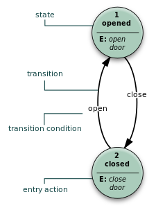
A finite-state machine (FSM) or finite-state automaton, finite automaton, or simply a state machine, is a mathematical model of computation. It is an abstract machine that can be in exactly one of a finite number of states at any given time. The FSM can change from one state to another in response to some inputs; the change from one state to another is called a transition. An FSM is defined by a list of its states, its initial state, and the inputs that trigger each transition. Finite-state machines are of two types—deterministic finite-state machines and non-deterministic finite-state machines. For any non-deterministic finite-state machine, an equivalent deterministic one can be constructed.

<span class="mw-page-title-main">Pushdown automaton</span> Type of automaton

In the theory of computation, a branch of theoretical computer science, a pushdown automaton (PDA) is a type of automaton that employs a stack.

A tree automaton is a type of state machine. Tree automata deal with tree structures, rather than the strings of more conventional state machines.

<span class="mw-page-title-main">Automata theory</span> Study of abstract machines and automata

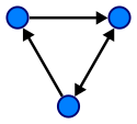
Automata theory is the study of abstract machines and automata, as well as the computational problems that can be solved using them. It is a theory in theoretical computer science with close connections to mathematical logic. The word automata comes from the Greek word αὐτόματος, which means "self-acting, self-willed, self-moving". An automaton is an abstract self-propelled computing device which follows a predetermined sequence of operations automatically. An automaton with a finite number of states is called a Finite Automaton (FA) or Finite-State Machine (FSM). The figure on the right illustrates a finite-state machine, which is a well-known type of automaton. This automaton consists of states and transitions. As the automaton sees a symbol of input, it makes a transition to another state, according to its transition function, which takes the previous state and current input symbol as its arguments.

In the theory of computation, a Mealy machine is a finite-state machine whose output values are determined both by its current state and the current inputs. This is in contrast to a Moore machine, whose output values are determined solely by its current state. A Mealy machine is a deterministic finite-state transducer: for each state and input, at most one transition is possible.

<span class="mw-page-title-main">Büchi automaton</span>

In computer science and automata theory, a deterministic Büchi automaton is a theoretical machine which either accepts or rejects infinite inputs. Such a machine has a set of states and a transition function, which determines which state the machine should move to from its current state when it reads the next input character. Some states are accepting states and one state is the start state. The machine accepts an input if and only if it will pass through an accepting state infinitely many times as it reads the input.

In the theory of computation, a Moore machine is a finite-state machine whose current output values are determined only by its current state. This is in contrast to a Mealy machine, whose output values are determined both by its current state and by the values of its inputs. Like other finite state machines, in Moore machines, the input typically influences the next state. Thus the input may indirectly influence subsequent outputs, but not the current or immediate output. The Moore machine is named after Edward F. Moore, who presented the concept in a 1956 paper, “Gedanken-experiments on Sequential Machines.”

<span class="mw-page-title-main">Deterministic finite automaton</span> Finite-state machine

In the theory of computation, a branch of theoretical computer science, a deterministic finite automaton (DFA)—also known as deterministic finite acceptor (DFA), deterministic finite-state machine (DFSM), or deterministic finite-state automaton (DFSA)—is a finite-state machine that accepts or rejects a given string of symbols, by running through a state sequence uniquely determined by the string. Deterministic refers to the uniqueness of the computation run. In search of the simplest models to capture finite-state machines, Warren McCulloch and Walter Pitts were among the first researchers to introduce a concept similar to finite automata in 1943.

In automata theory, a finite-state machine is called a deterministic finite automaton (DFA), if

A finite-state transducer (FST) is a finite-state machine with two memory tapes, following the terminology for Turing machines: an input tape and an output tape. This contrasts with an ordinary finite-state automaton, which has a single tape. An FST is a type of finite-state automaton (FSA) that maps between two sets of symbols. An FST is more general than an FSA. An FSA defines a formal language by defining a set of accepted strings, while an FST defines a relation between sets of strings.

Automata-based programming is a programming paradigm in which the program or part of it is thought of as a model of a finite-state machine (FSM) or any other formal automaton. Sometimes a potentially infinite set of possible states is introduced, and such a set can have a complicated structure, not just an enumeration.

In theoretical computer science, a pointer machine is an atomistic abstract computational machine whose storage structure is a graph. A pointer algorithm could also be an algorithm restricted to the pointer machine model.

In quantum computing, quantum finite automata (QFA) or quantum state machines are a quantum analog of probabilistic automata or a Markov decision process. They provide a mathematical abstraction of real-world quantum computers. Several types of automata may be defined, including measure-once and measure-many automata. Quantum finite automata can also be understood as the quantization of subshifts of finite type, or as a quantization of Markov chains. QFAs are, in turn, special cases of geometric finite automata or topological finite automata.

Automata-based programming is a programming technology. Its defining characteristic is the use of finite state machines to describe program behavior. The transition graphs of state machines are used in all stages of software development. Automata-based programming technology was introduced by Anatoly Shalyto in 1991. Switch-technology was developed to support automata-based programming. Automata-based programming is considered to be rather general purpose program development methodology than just another one finite state machine implementation.

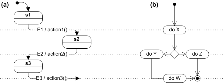
UML state machine, also known as UML statechart, is an extension of the mathematical concept of a finite automaton in computer science applications as expressed in the Unified Modeling Language (UML) notation.

In computer science and mathematical logic, an infinite-tree automaton is a state machine that deals with infinite tree structures. It can be seen as an extension of top-down finite-tree automata to infinite trees or as an extension of infinite-word automata to infinite trees.

In automata theory, a branch of theoretical computer science, an ω-automaton is a variation of a finite automaton that runs on infinite, rather than finite, strings as input. Since ω-automata do not stop, they have a variety of acceptance conditions rather than simply a set of accepting states.

In computational learning theory, induction of regular languages refers to the task of learning a formal description of a regular language from a given set of example strings. Although E. Mark Gold has shown that not every regular language can be learned this way, approaches have been investigated for a variety of subclasses. They are sketched in this article. For learning of more general grammars, see Grammar induction.

In theoretical computer science, in particular in formal language theory, Kleene's algorithm transforms a given nondeterministic finite automaton (NFA) into a regular expression. Together with other conversion algorithms, it establishes the equivalence of several description formats for regular languages. Alternative presentations of the same method include the "elimination method" attributed to Brzozowski and McCluskey, the algorithm of McNaughton and Yamada, and the use of Arden's lemma.

<span class="mw-page-title-main">Weighted automaton</span> Finite-state machine where edges carry weights

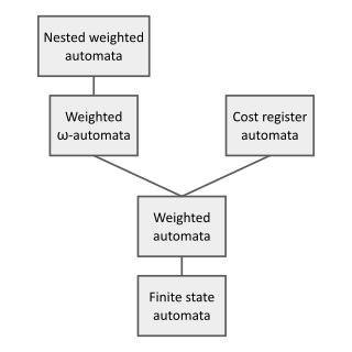
In theoretical computer science and formal language theory, a weighted automaton or weighted finite-state machine is a generalization of a finite-state machine in which the edges have weights, for example real numbers or integers. Finite-state machines are only capable of answering decision problems; they take as input a string and produce a Boolean output, i.e. either "accept" or "reject". In contrast, weighted automata produce a quantitative output, for example a count of how many answers are possible on a given input string, or a probability of how likely the input string is according to a probability distribution. They are one of the simplest studied models of quantitative automata.

References

  1. Archive index at the Wayback Machine
  2. 1 2 Taylor Booth (1967) Sequential Machines and Automata Theory, John Wiley and Sons, New York.
  3. 1 2 John Hopcroft and Jeffrey Ullman (1979) Introduction to Automata Theory, Languages, and Computation , Addison-Wesley Publishing Company, Reading Mass, ISBN   0-201-02988-X
  4. Edward J. McClusky, Introduction to the Theory of Switching Circuits, McGraw-Hill, 1965
  5. David Harel, Statecharts: A visual formalism for complex systems. Science of Computer Programming, 8(3):231–274, June 1987.
  6. Tiwari, A. (2002). Formal Semantics and Analysis Methods for Simulink Stateflow.
  7. Harel, D. (1987). A Visual Formalism for Complex Systems. Science of Computer Programming, 231–274.
  8. Alur, R., Kanade, A., Ramesh, S., & Shashidhar, K. C. (2008). Symbolic analysis for improving simulation coverage of Simulink/Stateflow models. International Conference on Embedded Software (pp. 89–98). Atlanta, GA: ACM.
  9. Samek, Miro (2008). Practical UML Statecharts in C/C++, Second Edition: Event-Driven Programming for Embedded Systems. Newnes. p. 728. ISBN   978-0-7506-8706-5.