
Synthetic-aperture radar (SAR) is a form of radar that is used to create two-dimensional images or three-dimensional reconstructions of objects, such as landscapes. SAR uses the motion of the radar antenna over a target region to provide finer spatial resolution than conventional stationary beam-scanning radars. SAR is typically mounted on a moving platform, such as an aircraft or spacecraft, and has its origins in an advanced form of side looking airborne radar (SLAR). The distance the SAR device travels over a target during the period when the target scene is illuminated creates the large synthetic antenna aperture. Typically, the larger the aperture, the higher the image resolution will be, regardless of whether the aperture is physical or synthetic – this allows SAR to create high-resolution images with comparatively small physical antennas. For a fixed antenna size and orientation, objects which are further away remain illuminated longer – therefore SAR has the property of creating larger synthetic apertures for more distant objects, which results in a consistent spatial resolution over a range of viewing distances.

3D radar provides for radar ranging and direction in three dimensions. In addition to range, the more common two-dimensional radar provides only azimuth for direction, whereas the 3D radar also provides elevation. Applications include weather monitoring, air defense, and surveillance.

A fire-control system (FCS) is a number of components working together, usually a gun data computer, a director and radar, which is designed to assist a ranged weapon system to target, track, and hit a target. It performs the same task as a human gunner firing a weapon, but attempts to do so faster and more accurately.
Secondary surveillance radar (SSR) is a radar system used in air traffic control (ATC), that unlike primary radar systems that measure the bearing and distance of targets using the detected reflections of radio signals, relies on targets equipped with a radar transponder, that reply to each interrogation signal by transmitting encoded data such as an identity code, the aircraft's altitude and further information depending on its chosen mode. SSR is based on the military identification friend or foe (IFF) technology originally developed during World War II; therefore, the two systems are still compatible. Monopulse secondary surveillance radar (MSSR), Mode S, TCAS and ADS-B are similar modern methods of secondary surveillance.

Gun laying is the process of aiming an artillery piece or turret, such as a gun, howitzer, or mortar, on land, at sea, or in air, against surface or aerial targets. It may be laying for either direct fire, where the gun is aimed directly at a target within the line-of-sight of the user, or by indirect fire, where the gun is not aimed directly at a target within the line-of-sight of the user. Indirect fire is determined from the information or data that is collected, calculated, and applied to physical coordinates to identify the location of the target by the user. The term includes automated aiming using, for example, radar-derived target data and computer-controlled guns.

A wind profiler is a type of weather observing equipment that uses radar or sound waves (SODAR) to detect the wind speed and direction at various elevations above the ground. Readings are made at each kilometer above sea level, up to the extent of the troposphere. Above this level there is inadequate water vapor present to produce a radar "bounce." The data synthesized from wind direction and speed is very useful to meteorological forecasting and timely reporting for flight planning. A twelve-hour history of data is available through NOAA websites.

High Angle Control System (HACS) was a British anti-aircraft fire-control system employed by the Royal Navy from 1931 and used widely during World War II. HACS calculated the necessary deflection required to place an explosive shell in the location of a target flying at a known height, bearing and speed.
In naval gunnery, when long-range guns became available, an enemy ship would move some distance after the shells were fired. It became necessary to figure out where the enemy ship, the target, was going to be when the shells arrived. The process of keeping track of where the ship was likely to be was called rangekeeping, because the distance to the target—the range—was a very important factor in aiming the guns accurately. As time passed, train, the direction to the target, also became part of rangekeeping, but tradition kept the term alive.

A radar display is an electronic device that presents radar data to the operator. The radar system transmits pulses or continuous waves of electromagnetic radiation, a small portion of which backscatter off targets and return to the radar system. The receiver converts all received electromagnetic radiation into a continuous electronic analog signal of varying voltage that can be converted then to a screen display.

The Iowa-class battleships are the most heavily armed warships the United States Navy has ever put to sea, due to the continual development of their onboard weaponry. The first Iowa-class ship was laid down in June 1940; in their World War II configuration, each of the Iowa-class battleships had a main battery of 16-inch (406 mm) guns that could hit targets nearly 20 statute miles (32 km) away with a variety of artillery shells designed for anti-ship or bombardment work. The secondary battery of 5-inch (127 mm) guns could hit targets nearly 9 statute miles (14 km) away with solid projectiles or proximity fuzed shells, and was effective in an anti-aircraft role as well. Each of the four battleships carried a wide array of 20 mm and 40 mm anti-aircraft guns for defense against enemy aircraft.

Wave radar is a type of radar for measuring wind waves. Several instruments based on a variety of different concepts and techniques are available, and these are all often called. This article, gives a brief description of the most common ground-based radar remote sensing techniques.

Ship gun fire-control systems (GFCS) are analogue fire-control systems that were used aboard naval warships prior to modern electronic computerized systems, to control targeting of guns against surface ships, aircraft, and shore targets, with either optical or radar sighting. Most US ships that are destroyers or larger employed gun fire-control systems for 5-inch (127 mm) and larger guns, up to battleships, such as Iowa class.
Gyro rate unit refers to a fire-control computer developed by the Royal Navy of the United Kingdom in 1937, and which was used extensively on British warships in World War II. In the 1930s the Royal Navy began to investigate the possibility of combining gyroscopes with optical sights to directly and accurately measure target aircraft speed and direction and began development of the GRU in 1937. A gyroscope was attached, via mechanical linkage, to an optical monocular sight to form the gyro rate unit or GRU.
Radar envelope is a critical Measure of Performance (MOP) identified in the Test and Evaluation Master Plan (TEMP). This is the volume of space where a radar system is required to reliably detect an object with a specific size and speed. This is one of the requirements that must be evaluated as part of the acceptance testing process.
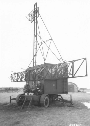
Radar, Gun Laying, Mark I, or GL Mk. I for short, was an early radar system developed by the British Army to provide range information to associated anti-aircraft artillery. There were two upgrades to the same basic system, GL/EF and GL Mk. II, both of which added the ability to accurately determine bearing and elevation.

The Type 277 was a surface search and secondary aircraft early warning radar used by the Royal Navy and allies during World War II and the post-war era. It was a major update of the earlier Type 271 radar, offering much more power, better signal processing, new displays, and new antennas with greatly improved performance and much simpler mounting requirements. It allowed a radar with performance formerly found only on cruisers and battleships to be fitted even to the smallest corvettes. It began to replace the 271 in 1943 and was widespread by the end of the year.

The AMES Type 82, also widely known by its rainbow codename Orange Yeoman, was an S-band 3D radar built by the Marconi Company and used by the Royal Air Force (RAF), initially for tactical control and later for air traffic control (ATC).
Martello is a family of phased array radar systems developed by Marconi Electronic Systems in the 1970s and introduced operationally in the early 1980s. They provided long-range early warning capabilities but also had the accuracy needed for interception plotting and "putting on" of other weapons systems like surface-to-air missiles. The name comes from the Martello towers that provided defence in earlier years.

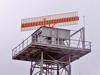
The cheese antenna, also known as a pillbox antenna, is a type of microwave-frequency parabolic antenna used in certain types of radar. The antenna consists of a cylindrical parabolic reflector consisting of sheet metal with a parabolic curve in one dimension and flat in the other, with metal plates covering the open sides, and a feed antenna, almost always some sort of feed horn, in front, pointing back toward the reflector. When the antenna is wide along its flat axis it is called a pillbox antenna and when narrow a cheese antenna. The name comes from the resulting antenna looking like a segment that has been cut from a wheel of cheese.

AN/SPS-8 is a two-dimensional radar manufactured by General Electric. It was used by the US Navy as a height finding radar after World War II, and was equipped aboard naval ships during the Cold War. Variants include AN/SPS-8A, AN-SPS/8B, AN/SPS-8C and AN/SPS-8D After modernization, it was redesignated as AN/SPS-30.
