Masonry (noun) is the building of structures from individual units, which are often laid in and bound together by mortar; the term masonry can also refer to the units themselves. The common materials of masonry construction are brick, building stone such as marble, granite, and limestone, cast stone, concrete block, glass block, and adobe. Masonry is generally a highly durable form of construction. However, the materials used, the quality of the mortar and workmanship, and the pattern in which the units are assembled can substantially affect the durability of the overall masonry construction. A person who constructs masonry is called a mason or bricklayer. These are both classified as construction trades.

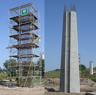
Reinforced concrete (RC) (also called reinforced cement concrete or RCC) is a composite material in which concrete's relatively low tensile strength and ductility are counteracted by the inclusion of reinforcement having higher tensile strength or ductility. The reinforcement is usually, though not necessarily, steel reinforcing bars (rebar) and is usually embedded passively in the concrete before the concrete sets. Reinforcing schemes are generally designed to resist tensile stresses in particular regions of the concrete that might cause unacceptable cracking and/or structural failure. Modern reinforced concrete can contain varied reinforcing materials made of steel, polymers or alternate composite material in conjunction with rebar or not. Reinforced concrete may also be permanently stressed, so as to improve the behaviour of the final structure under working loads. In the United States, the most common methods of doing this are known as pre-tensioning and post-tensioning.

Rebar, known when massed as reinforcing steel or reinforcement steel, is a steel bar or mesh of steel wires used as a tension device in reinforced concrete and reinforced masonry structures to strengthen and aid the concrete under tension. Concrete is strong under compression, but has weak tensile strength. Rebar significantly increases the tensile strength of the structure. Rebar's surface is often "deformed" with ribs, lugs or indentations to promote a better bond with the concrete and reduce the risk of slippage.

Retaining walls are relatively rigid walls used for supporting soil laterally so that it can be retained at different levels on the two sides. Retaining walls are structures designed to restrain soil to a slope that it would not naturally keep to. They are used to bound soils between two different elevations often in areas of terrain possessing undesirable slopes or in areas where the landscape needs to be shaped severely and engineered for more specific purposes like hillside farming or roadway overpasses. A retaining wall that retains soil on the backside and water on the frontside is called a seawall or a bulkhead.

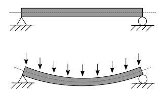
A beam is a structural element that primarily resists loads applied laterally to the beam's axis. Its mode of deflection is primarily by bending. The loads applied to the beam result in reaction forces at the beam's support points. The total effect of all the forces acting on the beam is to produce shear forces and bending moments within the beam, that in turn induce internal stresses, strains and deflections of the beam. Beams are characterized by their manner of support, profile, equilibrium conditions, length, and their material.

Seismic retrofitting is the modification of existing structures to make them more resistant to seismic activity, ground motion, or soil failure due to earthquakes. With better understanding of seismic demand on structures and with our recent experiences with large earthquakes near urban centers, the need of seismic retrofitting is well acknowledged. Prior to the introduction of modern seismic codes in the late 1960s for developed countries and late 1970s for many other parts of the world, many structures were designed without adequate detailing and reinforcement for seismic protection. In view of the imminent problem, various research work has been carried out. State-of-the-art technical guidelines for seismic assessment, retrofit and rehabilitation have been published around the world – such as the ASCE-SEI 41 and the New Zealand Society for Earthquake Engineering (NZSEE)'s guidelines. These codes must be regularly updated; the 1994 Northridge earthquake brought to light the brittleness of welded steel frames, for example.

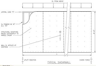
In structural engineering, a shear wall is a vertical element of a seismic force resisting system that is designed to resist in-plane lateral forces, typically wind and seismic loads. In many jurisdictions, the International Building Code and International Residential Code govern the design of shear walls.

Earthquake engineering is an interdisciplinary branch of engineering that designs and analyzes structures, such as buildings and bridges, with earthquakes in mind. Its overall goal is to make such structures more resistant to earthquakes. An earthquake engineer aims to construct structures that will not be damaged in minor shaking and will avoid serious damage or collapse in a major earthquake. Earthquake engineering is the scientific field concerned with protecting society, the natural environment, and the man-made environment from earthquakes by limiting the seismic risk to socio-economically acceptable levels. Traditionally, it has been narrowly defined as the study of the behavior of structures and geo-structures subject to seismic loading; it is considered as a subset of structural engineering, geotechnical engineering, mechanical engineering, chemical engineering, applied physics, etc. However, the tremendous costs experienced in recent earthquakes have led to an expansion of its scope to encompass disciplines from the wider field of civil engineering, mechanical engineering, nuclear engineering, and from the social sciences, especially sociology, political science, economics, and finance.

Steel frame is a building technique with a "skeleton frame" of vertical steel columns and horizontal I-beams, constructed in a rectangular grid to support the floors, roof and walls of a building which are all attached to the frame. The development of this technique made the construction of the skyscraper possible.

Formwork is temporary or permanent molds into which concrete or similar materials are poured. In the context of concrete construction, the falsework supports the shuttering molds.

Anchor bolts are used to connect structural and non-structural elements to the concrete. The connection is made by an assembling of different components such as: anchor bolts, steel plates, stiffeners. Anchor bolts transfer different types of load: tension forces and shear forces. A connection between structural elements can be represented by steel column attached to reinforced concrete foundation. Whereas, a common case of non-structural element attached to a structural one is represented by the connection between a facade system and a reinforced concrete wall.
Glass fiber reinforced concrete or GFRC is a type of fiber-reinforced concrete. The product is also known as glassfibre reinforced concrete or GRC in British English. Glass fiber concretes are mainly used in exterior building façade panels and as architectural precast concrete. Somewhat similar materials are fiber cement siding and cement boards.

In structural engineering, the tube is a system where, to resist lateral loads, a building is designed to act like a hollow cylinder, cantilevered perpendicular to the ground. This system was introduced by Fazlur Rahman Khan while at the architectural firm Skidmore, Owings & Merrill (SOM), in their Chicago office. The first example of the tube’s use is the 43-story Khan-designed DeWitt-Chestnut Apartment Building, since renamed Plaza on DeWitt, in Chicago, Illinois, finished in 1966.

A steel plate shear wall (SPSW) consists of steel infill plates bounded by boundary elements.

Voided biaxial slabs, sometimes called biaxial slabs, are a type of reinforced concrete slab which incorporates air-filled voids to reduce the volume of concrete required. These voids enable cheaper construction and less environmental impact. Another major benefit of the system is its reduction in slab weight compared with regular solid decks. Up to 50% of the slab volume may be removed in voids, resulting in less load on structural members. This also allows increased weight and/or span, since the self-weight of the slab contributes less to the overall load.

An anchor plate, floor plate or wall washer is a large plate or washer connected to a tie rod or bolt. Anchor plates are used on exterior walls of masonry buildings, for structural reinforcement. Being visible, many anchor plates are made in a style that is decorative.

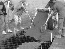
Cellular confinement systems (CCS)—also known as geocells—are widely used in construction for erosion control, soil stabilization on flat ground and steep slopes, channel protection, and structural reinforcement for load support and earth retention. Typical cellular confinement systems are geosynthetics made with ultrasonically welded high-density polyethylene (HDPE) strips or novel polymeric alloy (NPA)—and expanded on-site to form a honeycomb-like structure—and filled with sand, soil, rock, gravel or concrete.

A T-beam, used in construction, is a load-bearing structure of reinforced concrete, wood or metal, with a T-shaped cross section. The top of the T-shaped cross section serves as a flange or compression member in resisting compressive stresses. The web of the beam below the compression flange serves to resist shear stress and to provide greater separation for the coupled forces of bending.
The Filigree Wideslab method is a process for construction of concrete floor decks from two interconnected concrete placements, one precast in a factory, and the other done in the field. The method was developed during the late 1960s by Harry H. Wise as a more efficient and economic construction process than conventional cast-in-place technologies.
The infill wall is the supported wall that closes the perimeter of a building constructed with a three-dimensional framework structure. Therefore, the structural frame ensures the bearing function, whereas the infill wall serves to separate inner and outer space, filling up the boxes of the outer frames. The infill wall has the unique static function to bear its own weight. The infill wall is an external vertical opaque type of closure. With respect to other categories of wall, the infill wall differs from the partition that serves to separate two interior spaces, yet also non-load bearing, and from the load bearing wall. The latter performs the same functions of the infill wall, hygro-thermically and acoustically, but performs static functions too.


