Related Research Articles

Paper size standards govern the size of sheets of paper used as writing paper, stationery, cards, and for some printed documents.

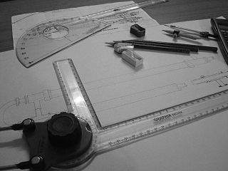
An engineering drawing is a type of technical drawing that is used to convey information about an object. A common use is to specify the geometry necessary for the construction of a component and is called a detail drawing. Usually, a number of drawings are necessary to completely specify even a simple component. These drawings are linked together by a "master drawing." This "master drawing" is more commonly known as an assembly drawing. The assembly drawing gives the drawing numbers of the subsequent detailed components, quantities required, construction materials and possibly 3D images that can be used to locate individual items. Although mostly consisting of pictographic representations, abbreviations and symbols are used for brevity and additional textual explanations may also be provided to convey the necessary information.

Geometric dimensioning and tolerancing (GD&T) is a system for defining and communicating engineering tolerances via a symbolic language on engineering drawings and computer-generated 3D models that describes a physical object's nominal geometry and the permissible variation thereof. GD&T is used to define the nominal geometry of parts and assemblies, the allowable variation in size, form, orientation, and location of individual features, and how features may vary in relation to one another such that a component is considered satisfactory for its intended use. Dimensional specifications define the nominal, as-modeled or as-intended geometry, while tolerance specifications define the allowable physical variation of individual features of a part or assembly.

Engineering tolerance is the permissible limit or limits of variation in:
- a physical dimension;
- a measured value or physical property of a material, manufactured object, system, or service;
- other measured values ;
- in engineering and safety, a physical distance or space (tolerance), as in a truck (lorry), train or boat under a bridge as well as a train in a tunnel ;
- in mechanical engineering, the space between a bolt and a nut or a hole, etc.

A hole punch, also known as hole puncher, or paper puncher, is an office tool that is used to create holes in sheets of paper, often for the purpose of collecting the sheets in a binder or folder. A hole punch can also refer to similar tools for other materials, such as leather, cloth, or plastic or metal sheets.

A screw thread is a helical structure used to convert between rotational and linear movement or force. A screw thread is a ridge wrapped around a cylinder or cone in the form of a helix, with the former being called a straight thread and the latter called a tapered thread. A screw thread is the essential feature of the screw as a simple machine and also as a threaded fastener.

A go/no-go gauge refers to an inspection tool used to check a workpiece against its allowed tolerances via a go/no-go test. Its name is derived from two tests: the check involves the workpiece having to pass one test (go) and fail the other (no-go).
An interference fit, also known as a pressed fit or friction fit, is a form of fastening between two tightfitting mating parts that produces a joint which is held together by friction after the parts are pushed together.
Nominal Pipe Size (NPS) is a North American set of standard sizes for pipes used for high or low pressures and temperatures. "Nominal" refers to pipe in non-specific terms and identifies the diameter of the hole with a non-dimensional number. Specific pipe is identified by pipe diameter and another non-dimensional number for wall thickness referred to as the Schedule. NPS is often incorrectly called National Pipe Size, due to confusion with the American standard for pipe threads, "national pipe straight", which also abbreviates as "NPS". The European and international designation equivalent to NPS is DN, in which sizes are measured in millimetres, see ISO 6708. The term NB is also frequently used interchangeably with DN.
The ISO metric screw thread is the most commonly used type of general-purpose screw thread worldwide. They were one of the first international standards agreed when the International Organization for Standardization (ISO) was set up in 1947.
When two probability distributions overlap, statistical interference exists. Knowledge of the distributions can be used to determine the likelihood that one parameter exceeds another, and by how much.
Engineering fits are generally used as part of geometric dimensioning and tolerancing when a part or assembly is designed. In engineering terms, the "fit" is the clearance between two mating parts, and the size of this clearance determines whether the parts can, at one end of the spectrum, move or rotate independently from each other or, at the other end, are temporarily or permanently joined. Engineering fits are generally described as a "shaft and hole" pairing, but are not necessarily limited to just round components. ISO is the internationally accepted standard for defining engineering fits, but ANSI is often still used in North America.
In engineering and machining, an allowance is a planned deviation between an exact dimension and a nominal or theoretical dimension, or between an intermediate-stage dimension and an intended final dimension. The unifying abstract concept is that a certain amount of difference allows for some known factor of compensation or interference. For example, an area of excess metal may be left because it is needed to complete subsequent machining. Common cases are listed below. An allowance, which is a planned deviation from an ideal, is contrasted with a tolerance, which accounts for expected but unplanned deviations.
The distinction between real value and nominal value occurs in many fields. From a philosophical viewpoint, nominal value represents an accepted condition, which is a goal or an approximation, as opposed to the real value, which is always present.
Tolerance analysis is the general term for activities related to the study of accumulated variation in mechanical parts and assemblies. Its methods may be used on other types of systems subject to accumulated variation, such as mechanical and electrical systems. Engineers analyze tolerances for the purpose of evaluating geometric dimensioning and tolerancing (GD&T). Methods include 2D tolerance stacks, 3D Monte Carlo simulations, and datum conversions.
ISO 128 is an international standard (ISO), about the general principles of presentation in technical drawings, specifically the graphical representation of objects on technical drawings.
C11 is an informal name for ISO/IEC 9899:2011, a past standard for the C programming language. It replaced C99 and has been superseded by C17. C11 mainly standardizes features already supported by common contemporary compilers, and includes a detailed memory model to better support multiple threads of execution. Due to delayed availability of conforming C99 implementations, C11 makes certain features optional, to make it easier to comply with the core language standard.
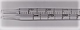
A graduated pipette is a pipette with its volume, in increments, marked along the tube. It is used to accurately measure and transfer a volume of liquid from one container to another. It is made from plastic or glass tubes and has a tapered tip. Along the body of the tube are graduation markings indicating volume from the tip to that point. A small pipette allows for more precise measurement of fluids; a larger pipette can be used to measure volumes when the accuracy of the measurement is less critical. Accordingly, pipettes vary in volume, with most measuring between 0 and 25.0 millilitres.
Preferred metric sizes are a set of international standards and de facto standards that are designed to make using the metric system easier and simpler, especially in engineering and construction practices. One of the methods used to arrive at these preferred sizes is the use of preferred numbers and convenient numbers, such as the Renard series and 1-2-5 series, to limit the number of different sizes of components needed.
Geometrical Product Specification and Verification (GPS&V) is a set of ISO standards developed by ISO Technical Committee 213. The aim of those standards is to develop a common language to specify macro geometry and micro-geometry of products or parts of products so that the language can be used consistently worldwide.
References
- ↑ International Organization for Standardization. ISO 286-1:2010 Geometrical product specifications (GPS) - ISO code system for tolerances on linear sizes, Part 1. p. 20.
- ↑ Ibid. p. 12
- ↑ Ibid. p. 28