The impulse excitation technique (IET) is a non-destructive material characterization technique to determine the elastic properties and internal friction of a material of interest. [1] It measures the resonant frequencies in order to calculate the Young's modulus, shear modulus, Poisson's ratio and internal friction of predefined shapes like rectangular bars, cylindrical rods and disc shaped samples. The measurements can be performed at room temperature or at elevated temperatures (up to 1700 °C) under different atmospheres. [2]
The measurement principle is based on tapping the sample with a small projectile and recording the induced vibration signal with a piezoelectric sensor, microphone, laser vibrometer or accelerometer. To optimize the results a microphone or a laser vibrometer can be used as there is no contact between the test-piece and the sensor. Laser vibrometers are preferred to measure signals in vacuum. Afterwards, the acquired vibration signal in the time domain is converted to the frequency domain by a fast Fourier transformation. Dedicated software will determine the resonant frequency with high accuracy to calculate the elastic properties based on the classical beam theory. [3]
Different resonant frequencies can be excited dependent on the position of the support wires, the mechanical impulse and the microphone. The two most important resonant frequencies are the flexural which is controlled by the Young's modulus of the sample and the torsional which is controlled by the shear modulus for isotropic materials.
For predefined shapes like rectangular bars, discs, rods and grinding wheels, dedicated software calculates the sample's elastic properties using the sample dimensions, weight and resonant frequency (ASTM E1876-15).
The first figure gives an example of a test-piece vibrating in the flexure mode. This induced vibration is also referred as the out-of-plane vibration mode. The in-plane vibration will be excited by turning the sample 90° on the axis parallel to its length. The natural frequency of this flexural vibration mode is characteristic for the dynamic Young's modulus. To minimize the damping of the test-piece, it has to be supported at the nodes where the vibration amplitude is zero. The test-piece is mechanically excited at one of the anti-nodes to cause maximum vibration.
The second figure gives an example of a test-piece vibrating in the torsion mode. The natural frequency of this vibration is characteristic for the shear modulus. To minimize the damping of the test-piece, it has to be supported at the center of both axis. The mechanical excitation has to be performed in one corner in order to twist the beam rather than flexing it.
The Poisson's ratio is a measure in which a material tends to expand in directions perpendicular to the direction of compression. After measuring the Young's modulus and the shear modulus, dedicated software determines the Poisson's ratio using Hooke's law which can only be applied to isotropic materials according to the different standards.
Material damping or internal friction is characterized by the decay of the vibration amplitude of the sample in free vibration as the logarithmic decrement. The damping behaviour originates from anelastic processes occurring in a strained solid i.e. thermoelastic damping, magnetic damping, viscous damping, defect damping, ... For example, different materials defects (dislocations, vacancies, ...) can contribute to an increase in the internal friction between the vibrating defects and the neighboring regions.
Considering the importance of elastic properties for design and engineering applications, a number of experimental techniques are developed and these can be classified into 2 groups; static and dynamic methods. Statics methods (like the four-point bending test and nanoindentation) are based on direct measurements of stresses and strains during mechanical tests. Dynamic methods (like ultrasound spectroscopy and impulse excitation technique) provide an advantage over static methods because the measurements are relatively quick and simple and involve small elastic strains. Therefore, IET is very suitable for porous and brittle materials like ceramics and refractories. The technique can also be easily modified for high temperature experiments and only a small amount of material needs to be available.
The most important parameters to define the measurement uncertainty are the mass and dimensions of the sample. Therefore, each parameter has to be measured (and prepared) to a level of accuracy of 0.1%. Especially, the sample thickness is most critical (third power in the equation for Young's modulus). In that case, an overall accuracy of 1% can be obtained practically in most applications.
The impulse excitation technique can be used in a wide range of applications. Nowadays, IET equipment can perform measurements between −50 °C and 1700 °C in different atmospheres (air, inert, vacuum). IET is mostly used in research and as quality control tool to study the transitions as function of time and temperature. A detailed insight into the material crystal structure can be obtained by studying the elastic and damping properties. For example, the interaction of dislocations and point defects in carbon steels are studied. [4] Also the material damage accumulated during a thermal shock treatment can be determined for refractory materials. [5] This can be an advantage in understanding the physical properties of certain materials. Finally, the technique can be used to check the quality of systems. In this case, a reference piece is required to obtain a reference frequency spectrum. Engine blocks for example can be tested by tapping them and comparing the recorded signal with a pre-recorded signal of a reference engine block. By using simple cluster analysis algorithms or principal component analysis, sample's pattern recognition is also achievable with a set of pre-recorded signals. [6]
with
with
G the shear modulus
with
with
If the Young's modulus and shear modulus are known, the Poisson's ratio can be calculated according to:
The induced vibration signal (in the time domain) is fitted as a sum of exponentially damped sinusoidal functions according to:
with
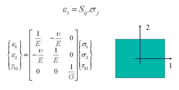
Isotropic elastic properties can be found by IET using the above described empirical formulas for the Young's modulus E, the shear modulus G and Poisson's ratio v. For isotropic materials the relation between strains and stresses in any point of flat sheets is given by the flexibility matrix [S] in the following expression:
In this expression, ε1 and ε2 are normal strains in the 1- and 2-direction and Υ12 is the shear strain. σ1 and σ2 are the normal stresses and τ12 is the shear stress. The orientation of the axes 1 and 2 in the above figure is arbitrary. This means that the values for E, G and v are the same in any material direction.
More complex material behaviour like orthotropic material behaviour can be identified by extended IET procedures. A material is called orthotropic when the elastic properties are symmetric with respect to a rectangular Cartesian system of axes. In case of a two dimensional state of stress, like in thin sheets, the stress-strain relations for orthotropic material become:
E1 and E2 are the Young's moduli in the 1- and 2-direction and G12 is the in-plane shear modulus. v12 is the major Poisson's ratio and v21 is the minor Poisson's ratio. The flexibility matrix [S] is symmetric. The minor Poisson's ratio can hence be found if E1, E2 and v12 are known.
The figure above shows some examples of common orthotropic materials: layered uni-directionally reinforced composites with fiber directions parallel to the plate edges, layered bi-directionally reinforced composites, short fiber reinforced composites with preference directions (like wooden particle boards), plastics with preference orientation, rolled metal sheets, and much more...
Standard methods for the identification of the two Young's moduli E1 and E2 require two tensile, bending of IET tests, one on a beam cut along the 1-direction and one on a beam cut along the 2-direction. Major and minor Poisson's ratios can be identified if also the transverse strains are measured during the tensile tests. The identification of the in-plane shear modulus requires an additional in plane shearing test.
The "Resonalyser procedure" [7] [8] [9] [10] is an extension of the IET using an inverse method (also called "Mixed numerical experimental method"). The non destructive Resonalyser procedure allows a fast and accurate simultaneous identification of the 4 Engineering constants E1, E2, G12 and v12 for orthotropic materials. For the identification of the four orthotropic material constants, the first three natural frequencies of a rectangular test plate with constant thickness and the first natural frequency of two test beams with rectangular cross section must be measured. One test beam is cut along the longitudinal direction 1, the other one cut along the transversal direction 2 (see Figure on the right).
The Young's modulus of the test beams can be found using the bending IET formula for test beams with a rectangular cross section.
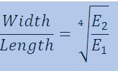
The ratio Width/Length of the test plate must be cut according to the following formula:
This ratio yields a so-called "Poisson plate". The interesting property of a Freely suspended Poisson plate is that the modal shapes that are associated with the 3 first resonance frequencies are fixed: the first resonance frequency is associated with a torsional modal shape, the second resonance frequency is associated with a saddle modal shape and the third resonance frequency is associated with a breathing modal shape.
So, without the necessity to do an investigation to the nature of the modal shapes, the IET on a Poisson plate reveals the vibrational behaviour of a Poisson plate.
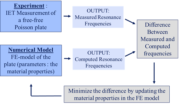
The question is now how to extract the orthotropic Engineering constants from the frequencies measured with IET on the beams and Poisson plate. This problem can be solved by an inverse method (also called" Mixed numerical/experimental method" [11] ) based on a finite element (FE) computer model of the Poisson plate. A FE model allows computing resonance frequencies for a given set of material properties
In an inverse method, the material properties in the finite element model are updated in such a way that the computed resonance frequencies match the measured resonance frequencies.
Problems with inverse methods are:
· The need of good starting values for the material properties
· Are the parameters converging to the correct physical solution?
· Is the solution unique?
The requirements to obtain good results are:
In the case the Young's moduli (obtained by IET) are fixed (as non variable parameters) in the inverse method procedure and if only the Poisson's ratio v12 and the in-plane shear modulus G12 are taken as variable parameters in the FE-model, the Resonalyser procedure satisfies all above requirements.
Indeed,
A viscometer is an instrument used to measure the viscosity of a fluid. For liquids with viscosities which vary with flow conditions, an instrument called a rheometer is used. Thus, a rheometer can be considered as a special type of viscometer. Viscometers can measure only constant viscosity, that is, viscosity that does not change with flow conditions.
The speed of sound is the distance travelled per unit of time by a sound wave as it propagates through an elastic medium. At 20 °C (68 °F), the speed of sound in air is about 343 m/s, or one km in 2.91 s or one mile in 4.69 s. It depends strongly on temperature as well as the medium through which a sound wave is propagating. At 0 °C (32 °F), the speed of sound in air is about 331 m/s. More simply, the speed of sound is how fast vibrations travel.
Young's modulus is a mechanical property of solid materials that measures the tensile or compressive stiffness when the force is applied lengthwise. It is the modulus of elasticity for tension or axial compression. Young's modulus is defined as the ratio of the stress applied to the object and the resulting axial strain in the linear elastic region of the material.
In materials science and solid mechanics, Poisson's ratio (nu) is a measure of the Poisson effect, the deformation of a material in directions perpendicular to the specific direction of loading. The value of Poisson's ratio is the negative of the ratio of transverse strain to axial strain. For small values of these changes, is the amount of transversal elongation divided by the amount of axial compression. Most materials have Poisson's ratio values ranging between 0.0 and 0.5. For soft materials, such as rubber, where the bulk modulus is much higher than the shear modulus, Poisson's ratio is near 0.5. For open-cell polymer foams, Poisson's ratio is near zero, since the cells tend to collapse in compression. Many typical solids have Poisson's ratios in the range of 0.2–0.3. The ratio is named after the French mathematician and physicist Siméon Poisson.
Dynamic mechanical analysis is a technique used to study and characterize materials. It is most useful for studying the viscoelastic behavior of polymers. A sinusoidal stress is applied and the strain in the material is measured, allowing one to determine the complex modulus. The temperature of the sample or the frequency of the stress are often varied, leading to variations in the complex modulus; this approach can be used to locate the glass transition temperature of the material, as well as to identify transitions corresponding to other molecular motions.
An elastic modulus is the unit of measurement of an object's or substance's resistance to being deformed elastically when a stress is applied to it.
Stiffness is the extent to which an object resists deformation in response to an applied force.
In materials science and continuum mechanics, viscoelasticity is the property of materials that exhibit both viscous and elastic characteristics when undergoing deformation. Viscous materials, like water, resist shear flow and strain linearly with time when a stress is applied. Elastic materials strain when stretched and immediately return to their original state once the stress is removed.
In structural engineering, buckling is the sudden change in shape (deformation) of a structural component under load, such as the bowing of a column under compression or the wrinkling of a plate under shear. If a structure is subjected to a gradually increasing load, when the load reaches a critical level, a member may suddenly change shape and the structure and component is said to have buckled. Euler's critical load and Johnson's parabolic formula are used to determine the buckling stress of a column.
In applied mechanics, bending characterizes the behavior of a slender structural element subjected to an external load applied perpendicularly to a longitudinal axis of the element.
Thermal shock is a phenomenon characterized by a rapid change in temperature that results in a transient mechanical load on an object. The load is caused by the differential expansion of different parts of the object due to the temperature change. This differential expansion can be understood in terms of strain, rather than stress. When the strain exceeds the tensile strength of the material, it can cause cracks to form and eventually lead to structural failure.
In materials science, shear modulus or modulus of rigidity, denoted by G, or sometimes S or μ, is a measure of the elastic shear stiffness of a material and is defined as the ratio of shear stress to the shear strain:
Dynamic modulus is the ratio of stress to strain under vibratory conditions. It is a property of viscoelastic materials.
Nanoindentation, also called instrumented indentation testing, is a variety of indentation hardness tests applied to small volumes. Indentation is perhaps the most commonly applied means of testing the mechanical properties of materials. The nanoindentation technique was developed in the mid-1970s to measure the hardness of small volumes of material.
The Timoshenko–Ehrenfest beam theory was developed by Stephen Timoshenko and Paul Ehrenfest early in the 20th century. The model takes into account shear deformation and rotational bending effects, making it suitable for describing the behaviour of thick beams, sandwich composite beams, or beams subject to high-frequency excitation when the wavelength approaches the thickness of the beam. The resulting equation is of 4th order but, unlike Euler–Bernoulli beam theory, there is also a second-order partial derivative present. Physically, taking into account the added mechanisms of deformation effectively lowers the stiffness of the beam, while the result is a larger deflection under a static load and lower predicted eigenfrequencies for a given set of boundary conditions. The latter effect is more noticeable for higher frequencies as the wavelength becomes shorter, and thus the distance between opposing shear forces decreases.
Lamb waves propagate in solid plates or spheres. They are elastic waves whose particle motion lies in the plane that contains the direction of wave propagation and the direction perpendicular to the plate. In 1917, the English mathematician Horace Lamb published his classic analysis and description of acoustic waves of this type. Their properties turned out to be quite complex. An infinite medium supports just two wave modes traveling at unique velocities; but plates support two infinite sets of Lamb wave modes, whose velocities depend on the relationship between wavelength and plate thickness.
Atomic force acoustic microscopy (AFAM) is a type of scanning probe microscopy (SPM). It is a combination of acoustics and atomic force microscopy. The principal difference between AFAM and other forms of SPM is the addition of a transducer at the bottom of the sample which induces longitudinal out-of-plane vibrations in the specimen. These vibrations are sensed by a cantilever and tip called a probe. The figure shown here is the clear schematic of AFAM principle here B is the magnified version of the tip and sample placed on the transducer and tip having some optical coating generally gold coating to reflect the laser light on to the photodiode.
The Zener ratio is a dimensionless number that is used to quantify the anisotropy for cubic crystals. It is sometimes referred as anisotropy ratio and is named after Clarence Zener. Conceptually, it quantifies how far a material is from being isotropic.
Solder fatigue is the mechanical degradation of solder due to deformation under cyclic loading. This can often occur at stress levels below the yield stress of solder as a result of repeated temperature fluctuations, mechanical vibrations, or mechanical loads. Techniques to evaluate solder fatigue behavior include finite element analysis and semi-analytical closed-form equations.
Anelasticity is a property of materials that describes their behaviour when undergoing deformation. Its formal definition does not include the physical or atomistic mechanisms but still interprets the anelastic behaviour as a manifestation of internal relaxation processes. It is a behaviour differing from elastic behaviour.
{{cite journal}}
: CS1 maint: multiple names: authors list (link){{cite book}}
: CS1 maint: others (link){{cite web}}
: CS1 maint: multiple names: authors list (link)