A suspension bridge is a type of bridge in which the deck is hung below suspension cables on vertical suspenders. The first modern examples of this type of bridge were built in the early 1800s. Simple suspension bridges, which lack vertical suspenders, have a long history in many mountainous parts of the world.

A crane is a machine used to move materials both vertically and horizontally, utilizing a system of a boom, hoist, wire ropes or chains, and sheaves for lifting and relocating heavy objects within the swing of its boom. The device uses one or more simple machines, such as the lever and pulley, to create mechanical advantage to do its work. Cranes are commonly employed in transportation for the loading and unloading of freight, in construction for the movement of materials, and in manufacturing for the assembling of heavy equipment.

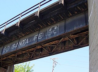
A plate girder bridge is a bridge supported by two or more plate girders.

A box girder bridge, or box section bridge, is a bridge in which the main beams comprise girders in the shape of a hollow box. The box girder normally comprises prestressed concrete, structural steel, or a composite of steel and reinforced concrete. The box is typically rectangular or trapezoidal in cross-section. Box girder bridges are commonly used for highway flyovers and for modern elevated structures of light rail transport. Although the box girder bridge is normally a form of beam bridge, box girders may also be used on cable-stayed and other bridges.

The eastern span replacement of the San Francisco–Oakland Bay Bridge was a construction project to replace a seismically unsound portion of the Bay Bridge with a new self-anchored suspension bridge (SAS) and a pair of viaducts. The bridge is in the U.S. state of California and crosses the San Francisco Bay between Yerba Buena Island and Oakland. The span replacement took place between 2002 and 2013, and is the most expensive public works project in California history, with a final price tag of $6.5 billion, a 2,500% increase from the original estimate of $250 million, which was an initial estimate for a seismic retrofit of the span, not the full span replacement ultimately completed. Originally scheduled to open in 2007, several problems delayed the opening until September 2, 2013. With a width of 258.33 ft (78.74 m), comprising 10 general-purpose lanes, it is the world's widest bridge according to Guinness World Records.

The Narrows Bridge is a freeway and railway crossing of the Swan River in Perth, Western Australia.

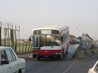
The medium girder bridge (MGB) is a lightweight, man-portable bridge that can be assembled without help from heavy equipment. In addition, it is also a deck type, two-girder bridging system capable of carrying loads up to and including main battle tanks (MBT).

The Bandra–Worli Sea Link is a 5.6 km long, 8-lane wide cable-stayed bridge that links Bandra in the Western Suburbs of Mumbai with Worli in South Mumbai. It is the second longest sea bridge after Mumbai Trans Harbour Link, as well as the 5th longest bridge in India after Mumbai Trans Harbour Link, Bhupen Hazarika Setu, Dibang River Bridge and Mahatma Gandhi Setu. It contains pre-stressed concrete-steel viaducts on either side. It was planned as a part of the proposed Western Freeway that would link the Western Suburbs to Nariman Point in Mumbai's main business district, but is now planned to become part of the Coastal Road to Kandivali.

The M5 is an expressway in the City of Cape Town Metropolitan Municipality, South Africa. It connects Milnerton on the Western Seaboard in the north to Muizenberg in the south, and crosses both the N1 and the N2. For part of its length, from the N1 interchange to Plumstead, it is a limited-access freeway (motorway). From Mowbray to Muizenberg it is parallel to the M4 Main Road.

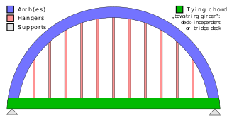
A tied-arch bridge is an arch bridge in which the outward-directed horizontal forces of the arch(es) are borne as tension by a chord tying the arch ends rather than by the ground or the bridge foundations. This strengthened chord may be the deck structure itself or consist of separate, independent tie-rods.

An overhead crane, commonly called a bridge crane, is a type of crane found in industrial environments. An overhead crane consists of two parallel rails seated on longitudinal I-beams attached to opposite steel columns by means of brackets. The traveling bridge spans the gap. A hoist, the lifting component of a crane, travels along the bridge. If the bridge is rigidly supported on two or more legs running on two fixed rails at ground level, the crane is called a gantry crane or a goliath crane.

The Mabey Logistic Support Bridge is a portable pre-fabricated truss bridge, designed for use by military engineering units to upgrade routes for heavier traffic, replace civilian bridges damaged by enemy action or floods etc., replace assault and general support bridges and to provide a long span floating bridge capability. The bridge is a variant of the Mabey Compact 200 bridge, with alterations made to suit the military user as well as a ramp system to provide ground clearance to civilian and military vehicles.

La Vicaria Bridge is a through arch bridge that spans the Segura River, where it meets La Fuensanta Reservoir near Yeste, in the province of Albacete, Spain. It forms part of a future road that will join Yeste with Letur and the neighbouring area to the east. The bridge has 2 vehicle lanes and 2 sidewalks.

The Surtees Bridge is a road bridge carrying the A66(T) road east west across the River Tees near Thornaby-on-Tees in the borough of Stockton-on-Tees in the north east of England. The bridge is situated one kilometre upriver from Stockton town centre, just upriver of Surtees Rail Bridge – a rail bridge carrying the Tees Valley Line. Built at a cost of £14.3 million the bridge replaces an earlier Surtees Bridge (1981) that showed signs of distress resulting from excessive settlement.

Vidyasagar Setu, also known as the Second Hooghly Bridge, is an 822.96-metre-long (2,700 ft) cable-stayed six-laned toll bridge over the Hooghly River in West Bengal, India, linking the cities of Kolkata and Howrah. Opened in 1992, Vidyasagar Setu was the first and longest cable-stayed bridge in India at the time of its inauguration. It was the second bridge to be built across the Hooghly River in Kolkata metropolitan region and was named after the education reformer Pandit Ishwar Chandra Vidyasagar. The project had a cost of ₹388 crore to build. The project was a joint effort between the public and private sectors, under the control of the Hooghly River Bridge Commissioners (HRBC).

This is a list of bridging and trackway equipment used by the Royal Engineers of the British Army. For more equipment in use with the Royal Engineers, see Modern equipment of the British Army.

The Geobukseon Bridge (Korean: 거북선대교), also called the Second Dolsan Bridge (제2돌산대교), is the main bridge on the Yeosu Road between Udu-ri, Dolsan and Jonghwa-dong, linking the Port of Yeosu with Dolsando across the Namhae sea. The bridge is floating cable-stayed bridge with 464m (35+82+230+82+35m) length and its construction started in June 2008. It opened in April 2012 and carries four lanes of motor vehicle traffic. The new link was intended to reduce traffic congestion on the First Dolsan Bridge which opened in 1985, and act as an important infra-structure link during the Yeosu Expo which had been held from May, 2012 for three months. The bridge was built by contractor Daelim Industrial Co. Ltd for client Iksan Regional Construction & Management Administration. Contract cost is US$60million, which includes a 460m long tunnel at one end, and a 280m long approach bridge.
The Harbor Bridge Project is the replacement of the existing through arch bridge that crosses the Corpus Christi Ship Channel, which serves the Port of Corpus Christi in Corpus Christi, Texas, with a modern cable-stayed bridge design. The route will connect with SH 286 at its southern terminus and US 181 on the north. Groundbreaking on construction took place on August 8, 2016 and was scheduled to be completed by the spring of 2020, but was extensively delayed by engineering and design issues, and is tentatively planned to be completed in 2025.

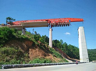
The SLJ900/32 or otherwise known as the Iron Monster is a superheavy launching gantry and one of the largest and most ubiquitous in the world. At over 90 meters in length, the SLJ900/32 is also one of the world's longest terrestrial vehicles. It is built by the Beijing Wowjoint Machinery Company and designed by the Shijiazhuang Railway Design Institute.

A movable scaffolding system (MSS) is a special-purpose self-launching form used in bridge construction, specifically prestressed concrete bridges with segments or spans that are cast in place. The movable scaffolding system is used to support a form while the concrete is cured; once the segment is complete, the scaffold and forms are moved to the end of the new segment and another segment is poured.


![Twin-girder upper-beam launching gantry, during construction of the Viaduc de Rogerville [fr] (completed 1996) A29 Viaduc Rogerville002.jpg](http://upload.wikimedia.org/wikipedia/commons/thumb/1/19/A29_Viaduc_Rogerville002.jpg/260px-A29_Viaduc_Rogerville002.jpg)


