MEMS magnetic actuator

Last updated

A MEMS magnetic actuator is a device that uses the microelectromechanical systems (MEMS) to convert an electric current into a mechanical output by employing the well-known Lorentz Force Equation or the theory of Magnetism.

Contents

Overview of MEMS

Micro-Electro-Mechanical System (MEMS) technology [1] is a process technology in which mechanical and electro-mechanical devices or structures are constructed using special micro-fabrication techniques. These techniques include: bulk micro-machining, surface micro-machining, LIGA, wafer bonding, etc.

MEMS scale of dimensions MEMS dimensions.jpg
MEMS scale of dimensions

A device is considered to be a MEMS device if it satisfies the following:

For the analysis of every MEMS device, the Lumped assumption is made: that if the size of the device is far less than the characteristic length scale of the phenomenon (wave or diffusion), then there would be no spatial variations across the entire device. Modelling becomes easy under this assumption. [2]

The Lumped Assumption Lumped Assumption.jpg
The Lumped Assumption

Operations in MEMS

The three major operations in MEMS are:

These three operations require some form of transduction schemes, the most popular ones being: piezoelectric, electrostatic, piezoresistive, electrodynamic, magnetic and magnetostrictive. The MEMS magnetic actuators use the last three schemes for their operation.

Magnetic actuation

The principle of magnetic actuation is based on the Lorentz Force Equation.

When a current-carrying conductor is placed in a static magnetic field, the field produced around the conductor interacts with the static field to produce a force. This force can be used to cause the displacement of a mechanical structure.

Magnetic actuation Magnetic Actuation.jpg
Magnetic actuation

Governing equations and parameters

A typical MEMS actuator is shown on the right. For a single turn of circular coil, the equations that govern its operation are: [3]

The deflection of a mechanical structure for actuation depends on certain parameters of the device. For actuation, there has to be an applied force and a restoring force. The applied force is the force represented by the equation above, while the restoring force is fixed by the spring constant of the moving structure.

The applied force depends on both the field from the coils and the magnet. The remanence value of the magnet, [4] its volume and position from the coils all contribute to its effect on the applied Force. Whereas the number of turns of coil, its size (radius) and the amount of current passing through it determines its effect on the Applied Force. The spring constant depends on the Young's Modulus of the moving structure, and its length, width and thickness.

Parameters1.jpg

Magnetostrictive actuators

Magnetic actuation is not limited to the use of Lorentz force to cause a mechanical displacement. Magnetostrictive actuators can also use the theory of magnetism to bring about displacement. Materials that change their shapes when exposed to magnetic fields can now be used to drive high-reliability linear motors and actuators..
An example is a nickel rod that tends to deform when it is placed in an external magnetic field. Another example is wrapping a series of electromagnetic induction coils around a metal tube in which a Terfenol-D material is placed. The coils generate a moving magnetic field that courses wavelike down the successive windings along the stator tube. As the traveling magnetic field causes each succeeding cross section of Terfenol-D to elongate, then contract when the field is removed, the rod will actually "crawl" down the stator tube like an inchworm. Repeated propagating waves of magnetic flux will translate the rod down the tube's length, producing a useful stroke and force output. The amount of motion generated by the material is proportional to the magnetic field provided by the coil system, which is a function of the electric current. This type of motive device, which features a single moving part, is called an elastic-wave or peristaltic linear motor. (view: Video of a Magnetostrictive micro walker)

Advantages of magnetic actuators

Magnet material

Magnet material selection for static B-Field Materialsm.jpg
Magnet material selection for static B-Field

The operation of the magnetic actuator depends on the interaction between the field from an electromagnet and a static field. To produce this static field, it is important to use the right material. In MEMS, permanent magnets have become the favorite because they have a very good scaling factor and they retain their magnetization even when there is no external field... meaning that they need not be continuously magnetized when they are in use [6] [7] [8] [9] [10]

Integrating the magnet into the MEMS device

As earlier discussed, MEMS devices are designed and fabricated using special micro-fabrication techniques. The major challenge however for magnetic MEMS is the integration of the magnet into the MEMS device. [11] [12] Recent research has suggested solutions to this challenge.

Fabrication (or molding) of the magnet

There are several ways by which the magnet could be fabricated on a MEMS structure:

Sputtering Sputtering1.jpg
Sputtering
Pulsed Layer Deposition Pulsed layer deposition.jpg
Pulsed Layer Deposition

Issues with magnetic actuation

Each of these challenges can be mitigated or lessened by the right choice of material, choice of molding or fabrication method, and the type of device that is to be constructed. Applications of the magnetic actuator include: the synthetic jet actuator, micro-pumps and micro-relays.

Related Research Articles

<span class="mw-page-title-main">MEMS</span> Very small devices that incorporate moving components

MEMS is the technology of microscopic devices incorporating both electronic and moving parts. MEMS are made up of components between 1 and 100 micrometres in size, and MEMS devices generally range in size from 20 micrometres to a millimetre, although components arranged in arrays can be more than 1000 mm2. They usually consist of a central unit that processes data and several components that interact with the surroundings.

<span class="mw-page-title-main">Magnet</span> Object that has a magnetic field

A magnet is a material or object that produces a magnetic field. This magnetic field is invisible but is responsible for the most notable property of a magnet: a force that pulls on other ferromagnetic materials, such as iron, steel, nickel, cobalt, etc. and attracts or repels other magnets.

<span class="mw-page-title-main">Magnetometer</span> Device that measures magnetism

A magnetometer is a device that measures magnetic field or magnetic dipole moment. Different types of magnetometers measure the direction, strength, or relative change of a magnetic field at a particular location. A compass is one such device, one that measures the direction of an ambient magnetic field, in this case, the Earth's magnetic field. Other magnetometers measure the magnetic dipole moment of a magnetic material such as a ferromagnet, for example by recording the effect of this magnetic dipole on the induced current in a coil.

<span class="mw-page-title-main">Electromagnet</span> Magnet created with an electric current

An electromagnet is a type of magnet in which the magnetic field is produced by an electric current. Electromagnets usually consist of wire wound into a coil. A current through the wire creates a magnetic field which is concentrated in the hole in the center of the coil. The magnetic field disappears when the current is turned off. The wire turns are often wound around a magnetic core made from a ferromagnetic or ferrimagnetic material such as iron; the magnetic core concentrates the magnetic flux and makes a more powerful magnet.

Magnetostriction is a property of magnetic materials that causes them to change their shape or dimensions during the process of magnetization. The variation of materials' magnetization due to the applied magnetic field changes the magnetostrictive strain until reaching its saturation value, λ. The effect was first identified in 1842 by James Joule when observing a sample of iron.

An actuator is a component of a machine that produces force, torque, or displacement, usually in a controlled way, when an electrical, pneumatic or hydraulic input is supplied to it in a system. An actuator converts such an input signal into the required form of mechanical energy. It is a type of transducer. In simple terms, it is a "mover".
<span class="mw-page-title-main">Reed switch</span> Electrical switch operated by an applied magnetic field

The reed switch is an electromechanical switch operated by an applied magnetic field. It was invented in 1922 by professor Valentin Kovalenkov at the Petrograd Electrotechnical University, and later evolved at Bell Telephone Laboratories in 1936 by Walter B. Ellwood into the reed relay. In its simplest and most common form, it consists of a pair of ferromagnetic flexible metal contacts in a hermetically sealed glass envelope. The contacts are usually normally open, closing when a magnetic field is present, or they may be normally closed and open when a magnetic field is applied. The switch may be actuated by an electromagnetic coil, making a reed relay, or by bringing a permanent magnet near it. When the magnetic field is removed, the contacts in the reed switch return to their original position. The "reed" is the metal part inside the reed switch envelope that is relatively thin and wide to make it flexible, resembling the reed of a musical instrument. The term "reed" may also include the external wire lead as well as the internal part.

Magnetic shape memory alloys (MSMAs), also called ferromagnetic shape memory alloys (FSMA), are particular shape memory alloys which produce forces and deformations in response to a magnetic field. The thermal shape memory effect has been obtained in these materials, too.

Terfenol-D, an alloy of the formula TbxDy1−xFe2 (x ≈ 0.3), is a magnetostrictive material. It was initially developed in the 1970s by the Naval Ordnance Laboratory in the United States. The technology for manufacturing the material efficiently was developed in the 1980s at Ames Laboratory under a U.S. Navy-funded program. It is named after terbium, iron (Fe), Naval Ordnance Laboratory (NOL), and the D comes from dysprosium.

<span class="mw-page-title-main">Ferrite (magnet)</span> Ferrimagnetic ceramic material composed of rust and a metallic element

A ferrite is a ceramic material made by mixing and firing iron(III) oxide with one or more additional metallic elements, such as strontium, barium, manganese, nickel, and zinc. They are ferrimagnetic, meaning they are attracted by magnetic fields and can be magnetized to become permanent magnets. Unlike other ferromagnetic materials, most ferrites are not electrically conductive, making them useful in applications like magnetic cores for transformers to suppress eddy currents. Ferrites can be divided into two families based on their resistance to being demagnetized.

Flux pumping is a method for magnetising superconductors to fields in excess of 15 teslas. The method can be applied to any type II superconductor and exploits a fundamental property of superconductors, namely their ability to support and maintain currents on the length scale of the superconductor. Conventional magnetic materials are magnetised on a molecular scale which means that superconductors can maintain a flux density orders of magnitude bigger than conventional materials. Flux pumping is especially significant when one bears in mind that all other methods of magnetising superconductors require application of a magnetic flux density at least as high as the final required field. This is not true of flux pumping.

Programmed magnets, or polymagnets are magnetic structures that incorporate correlated patterns of magnets with alternating polarity, designed to achieve a desired behavior and deliver stronger local force. By varying the magnetic fields and strengths, different mechanical behaviors can be controlled.

<span class="mw-page-title-main">Mechanical filter</span> Type of signal processing filter

A mechanical filter is a signal processing filter usually used in place of an electronic filter at radio frequencies. Its purpose is the same as that of a normal electronic filter: to pass a range of signal frequencies, but to block others. The filter acts on mechanical vibrations which are the analogue of the electrical signal. At the input and output of the filter, transducers convert the electrical signal into, and then back from, these mechanical vibrations.
<span class="mw-page-title-main">MEMS magnetic field sensor</span>

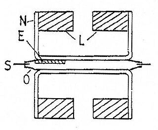
A MEMSmagnetic field sensor is a small-scale microelectromechanical systems (MEMS) device for detecting and measuring magnetic fields (Magnetometer). Many of these operate by detecting effects of the Lorentz force: a change in voltage or resonant frequency may be measured electronically, or a mechanical displacement may be measured optically. Compensation for temperature effects is necessary. Its use as a miniaturized compass may be one such simple example application.

<span class="mw-page-title-main">Magnetic levitation</span> Suspension of objects by magnetic force.

Magnetic levitation (maglev) or magnetic suspension is a method by which an object is suspended with no support other than magnetic fields. Magnetic force is used to counteract the effects of the gravitational force and any other forces.

<span class="mw-page-title-main">Microscanner</span>

A microscanner, or micro scanning mirror, is a microoptoelectromechanical system (MOEMS) in the category of micromirror actuators for dynamic light modulation. Depending upon the type of microscanner, the modulatory movement of a single mirror can be either translatory or rotational, on one or two axes. In the first case, a phase shifting effect takes place. In the second case, the incident light wave is deflected.

An electropermanent magnet or EPM is a type of permanent magnet in which the external magnetic field can be switched on or off by a pulse of electric current in a wire winding around part of the magnet. The magnet consists of two sections, one of "hard" magnetic material and one of "soft" material. The direction of magnetization in the latter piece can be switched by a pulse of current in a wire winding about the former. When the magnetically soft and hard materials have opposing magnetizations, the magnet produces no net external field across its poles, while when their direction of magnetization is aligned the magnet produces an external magnetic field.
In electromagnetism and materials science, the Jiles–Atherton model of magnetic hysteresis was introduced in 1984 by David Jiles and D. L. Atherton. This is one of the most popular models of magnetic hysteresis. Its main advantage is the fact that this model enables connection with physical parameters of the magnetic material. Jiles–Atherton model enables calculation of minor and major hysteresis loops. The original Jiles–Atherton model is suitable only for isotropic materials. However, an extension of this model presented by Ramesh et al. and corrected by Szewczyk enables the modeling of anisotropic magnetic materials.

<span class="mw-page-title-main">Magnetic gear</span>

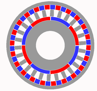
A magnetic gear resembles the traditional mechanical gear in geometry and function, using magnets instead of teeth. As two opposing magnets approach each other, they repel; when placed on two rings the magnets will act like teeth. As opposed to conventional hard contact backlash in a spur gear, where a gear may rotate freely until in contact with the next gear, the magnetic gear has a springy backlash. As a result magnetic gears are able to apply pressure no matter the relative angle. Although they provide a motion ratio as a traditional gear, such gears work without touching and are immune to wear of mating surfaces, have no noise, and may slip without damage.

In engineering, a solenoid is a device that converts electrical energy to mechanical energy, using an electromagnet formed from a coil of wire. The device creates a magnetic field from electric current, and uses the magnetic field to create linear motion. In electromagnetic technology, a solenoid is an actuator assembly with a sliding ferromagnetic plunger inside the coil. Without power, the plunger extends for part of its length outside the coil; applying power pulls the plunger into the coil. Electromagnets with fixed cores are not considered solenoids. In simple terms, a solenoid converts electrical energy into mechanical work. Typically, it has a multiturn coil of magnet wire surrounded by a frame, which is also a magnetic flux carrier to enhance its efficiency. In engineering, the term may also refer to a variety of transducer devices that convert energy into linear motion, more sophisticated than simple two–position actuators. The term "solenoid" also often refers to a solenoid valve, an integrated device containing an electromechanical solenoid which actuates either a pneumatic or hydraulic valve, or a solenoid switch, which is a specific type of relay that internally uses an electromechanical solenoid to operate an electrical switch; for example, an automobile starter solenoid or linear solenoid. Solenoid bolts, a type of electromechanical locking mechanism, also exist.

References

  1. Senturia, Stephen D. (2001). Microsystem Design. ISBN   978-0-7923-7246-2.
  2. Arnold, D. (Fall 2010 – Spring 2011). Lecture Notes on MEMS Transducers.
  3. Wagner, B.; w. Benecke. "Microfabricated Actuator with moving Permanent Magnet".{{cite journal}}: Cite journal requires |journal= (help)
  4. Dodrill, B. C.; B. J. Kelley. "Measurement with a VSM – Permanent Magnet Materials".{{cite journal}}: Cite journal requires |journal= (help)
  5. Arnold, D. "Permanent Magnets for MEMS".{{cite journal}}: Cite journal requires |journal= (help)
  6. Gibbs, M R J; E W Hill; P J Wright. "Magnetic Materials for MEMS Applications".{{cite journal}}: Cite journal requires |journal= (help)
  7. National Imports LLC. "Permanent Magnet Selection and Design Handbook".{{cite journal}}: Cite journal requires |journal= (help)
  8. Arnold, D. "Permanent Magnets for MEMS".{{cite journal}}: Cite journal requires |journal= (help)
  9. Wang, N. (2010). "Fabrication and Integration of Permanent Magnet Materials into MEMS Transducers". Bibcode:2010PhDT........49W.{{cite journal}}: Cite journal requires |journal= (help)
  10. Arnold, David. "Permanent magnets for MEMS".{{cite journal}}: Cite journal requires |journal= (help)
  11. Schiavone, Giuseppe; Desmulliez, Marc P. Y.; Walton, Anthony J. (2014-08-29). "Integrated Magnetic MEMS Relays: Status of the Technology". Micromachines. 5 (3): 622–653. doi: 10.3390/mi5030622 . hdl: 20.500.11820/0fe4a2e7-16d0-493d-bde2-9cfee7682ac3 .
  12. Chin, Tsung-Shune (2000). "Permanent magnet films for applications in Micro-electro-mechanical systems". Journal of Magnetism and Magnetic Materials. 209 (1): 75–79. Bibcode:2000JMMM..209...75C. doi:10.1016/S0304-8853(99)00649-6.
  13. Arnold, D.; B. Bowers; N. Wang (2008). "Wax-bonded NdFeB micromagnets for microelectromechanical systems applications". Journal of Applied Physics. 103 (7): 07E109. Bibcode:2008JAP...103gE109W. doi:10.1063/1.2830532.
  14. Wang, N. (2010). "Fabrication and Integration of Permanent Magnet Materials into MEMS Transducers". Bibcode:2010PhDT........49W.{{cite journal}}: Cite journal requires |journal= (help)
  15. Yang, Tzu-Shun; Naigang Wang; David P. Arnold (2011). "Fabrication and characterization of parylene-bonded Nd–Fe–B powder micromagnets". Journal of Applied Physics. 109 (7). Bibcode:2011JAP...109gA753Y. doi:10.1063/1.3566001.
  16. Guckel, H. "Progress in Magnetic Microactuators".{{cite journal}}: Cite journal requires |journal= (help)
  17. Gatzen, Hans H. "Advances in European Magnetic MEMS Technology".{{cite journal}}: Cite journal requires |journal= (help)