MPDS4

Last updated
MPDS4
Developer(s) CAD Schroer
Initial release2006
Stable release
5.2.1 / February 6, 2014 (2014-02-06)
Operating system MS Windows, Solaris
Available inMultilingual[ which? ]
Type Computer-aided design
License Proprietary
Website http://www.cad-schroer.com/

MPDS, the MEDUSA Plant Design System (known as MPDS4 since 2006), is a suite of plant engineering applications for 2D/3D layout, design and modelling of process plants, factories or installations. The systems history is closely tied to the very beginnings of mainstream CAD and the research culture fostered by Cambridge University and the UK government as well as the resulting "Cambridge Phenomenon " [1] MPDS was initially developed for 3D plant design and layout and piping design. Today, the software includes modules for 2D/3D factory layout, process, instrumentation diagrams (P&ID), mechanical handling systems design, steel design, ducting (HVAC) design, electrical design and hangers and supports Design. The latest version, MPDS4 5.2.1, was released for Microsoft Windows and Sun Solaris in February 2014.

Contents

History

MPDS’ history [2] is tied in with the Computer-Aided Design Centre (or CAD Centre) which was created in Cambridge in 1967 by the UK Government to carry out CAD research.

Famous British computer scientist Dr. Dick Newell worked there on a file-based macro language driven 3D plant design system called PDMS (Plant Design Management System). Together with colleague Tom Sancha he left the CAD Centre in 1977 to form a company called Cambridge Interactive Systems or CIS and primarily concentrated on 2D CAD. CIS had developed an electrical cabling solution initially called CABLOS, which was first purchased by Dowty Engineering in about 1979. Another early adopter was BMW, which used the system for car wiring diagrams. CABLOS soon became known and sold as the MEDUSA drafting system under CIS. The proprietary programming language with which MEDUSA version 1 was developed was known as baCIS 1. Around this time, the company also began developing its own 3D modelling kernel for MEDUSA.

Around 1980, CIS partnered with Prime Computer, a U.S.-based computer hardware provider. Prime had an option on the MEDUSA source code should CIS ever fail. In 1983 the U.S. CAD company ComputerVision purchased CIS.

ComputerVision/CIS started developing the MEDUSA Plant Design System (MPDS), the first plant design software based on a relational database. Developers knew from their prior experience with a file-based macro-language driven system that the next generation plant design system had to be built on a relational database and with a much more powerful programming language to handle large data volumes, complexity and relationships. Whereas mechanical CAD engineers were developing machinery with a few hundred or maybe a thousand components, plant design engineers typically needed to deal with hundreds of thousands of components. To facilitate this work, the baCIS 2 interpretive language and the MDB relational database were developed for MPDS. Existing MEDUSA technology was used to create the 2D and 3D geometric data required for plant layouts. The creation of this data-centric concept separated the 3D visualization of a plant from the underlying database and allowed engineers to plan and design installations with very large volumes of data, and produce all the required 2D drawings from 3D plant designs. [3]

The first MPDS sales date to around 1988 to NEI Parsons (Northern Engineering Industries later became part of the Rolls-Royce Industrial Power Group). Courtaulds Engineering, which had been using MEDUSA since 1983, was also an early MPDS adopter.

In the same year Prime Computer merged with ComputerVision and adopted the name ComputerVision to concentrate on software, due to declining hardware sales. MEDUSA continued to be developed throughout the 1990s in Cambridge, UK at ComputerVision's R&D Centre at Harston Mill.

In 1993, the next generation of MEDUSA and MPDS was released. What would have been version 13 was released as MEDUSA NG and MPDS NG. They signified the shift from tablet-driven menus to a graphical user interface, although tablets could still be used on that release.

In 1994 ComputerVision closed its R&D facility in Cambridge, moving to Boston, Massachusetts. As a result, five former ComputerVision staff members and MEDUSA experts formed the company Quintic Ltd in Cambridge, which continued to provide MEDUSA and MPDS development and consultancy services to ComputerVision and the MEDUSA customer base. Work included the porting of MEDUSA NG to Microsoft Windows.

Note: The above doesn't quite work. According to Companies House, Quintic Ltd was not actually formed until 27th February 2013, 19 years after the Cambridge R&D facility closed.

In 1998 the American CAD company Parametric Technology Corporation (PTC) acquired ComputerVision. The development partnership between Quintic and ComputerVision transferred to PTC.

The largest MEDUSA user base was in the heavily, manufacturing-driven, economy of Germany. CAD Schroer, a company founded in 1986 by Michael Schroer as a provider of CAD-based engineering services, became a MEDUSA vendor in 1988, having used the software extensively on client projects. The company, which also provided add-on modules and customizations, had established a development relationship first with ComputerVision, then with PTC.

In 2001, CAD Schroer acquired all rights to MEDUSA and MPDS from PTC. The development partnership between Quintic and CAD Schroer strengthened, as the two companies worked to create a Fourth Generation release of MEDUSA and MPDS. This included a complete overhaul of the functionality; the development of a graphical user interface (GUI) based on the Qt (framework) technology, the development of data exchange mechanisms and interfaces with third party systems, and the porting to the Linux open-source operating system.

In 2005, CAD Schroer acquired its development partner Quintic Ltd, gaining CAD development expertise that dates back to the days of CIS and Prime. CAD Schroer UK remains a software development center in Cambridge, whose staff continue to develop and support MEDUSA4 and MPDS4 in partnership with CAD development experts at CAD Schroer GmbH in Moers, Germany.

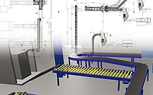
In 2006, CAD Schroer released the Fourth Generation of the MPDS plant design system, MPDS4. Since then the company has continued to develop and extend the functionality of the product suite, including the development of a factory layout module for designing 3D factories based on 2D drawings.

Technical Description

Database Architecture

Multi-user engineering design in MPDS is relational database-driven. The project database can be deployed as a central design database or as a project-specific database and contains component catalogs with assigned component attributes. The database drives the design graphics as well as user administration and can be integrated with other database-driven systems, such as Enterprise Resource Planning (ERP) system.

3D Graphics

MPDS combines use of the HOOPS 3D Graphics System with the relational database, whose catalog component attributes define the visual representation of each component. Because 3D plant models can be generated from catalog-based drawing routines, the demand on computer memory and resources is limited. Plants of hundreds of thousands of components can be designed, edited and exported to a compact .HSF format for external visual review. The system support varying display detail levels, allowing designers to visualize components either in great detail, visually simplified, or merely as an outline object in space, required for effective clash detection.

User Administration

Central user administration and access controls in MPDS allow Administrators to set up a variety of users who can work on a plant design simultaneously, and who can have different access privileges - limited, for example, to certain design disciplines or to certain areas within a plant. This is supported by integrated version and change management.

Quality Assurance

MPDS4 includes hard and soft clash detection, which can be applied to a whole project, to separate systems or between selected components. Consistency checking tools allow users to check work against specific design rules. Results can be passed to customizable reports, and components used in a design are automatically included in parts lists.

Modules

The MPDS4 Assembly Manager is at the core of the plant design and factory layout system, and can be extended with several user extensible and customizable modules covering plant engineering disciplines.

The MPDS4 Piping Design module delivers automated piping isometrics MPDS4 Piping.jpg
The MPDS4 Piping Design module delivers automated piping isometrics
PIPING DESIGN
MPDS4 PIPING DESIGN is an industrial piping design software add-on with extensive libraries of catalogue components to a variety of industrial standards, including DIN, ANSI and BS. Its routing tools are used for loading, positioning and replacing components, manually or automatically. The module supports P&ID-driven piping design and is pipe specification driven, so that only components from the same specification can be connected. MPDS4 PIPING DESIGN is fully integrated with ISOGEN (from ALIAS Piping Solutions) for automated piping isometric production.
P&ID
P&ID is an application for creating intelligent process and instrumentation diagrams; for data extraction, and for use of data to create and cross-check the 3D world. Design can be database-driven and based on existing parts lists. P&ID diagrams can be used to form the basis of 2D layouts and 3D designs, with the ability to cross-check P&IDs and automatically load P&ID components not yet included in a 3D plant design in the appropriate position.
MPDS4 Factory Layout offers a hybrid 2D/3D design environment MPDS4 Factory Layout.jpg
MPDS4 Factory Layout offers a hybrid 2D/3D design environment
FACTORY LAYOUT
MPDS4 FACTORY LAYOUT is a hybrid 2D/3D design environment where 2D layouts or drawings are used as the basis of 3D designs. Height attributes added to 2D building plans are used to produce 3D buildings. Symbols used in a 2D layout are linked to 3D model files which are automatically generated when users switch to 3D. Other components or product specials can be modelled using a sheet-based modelling approach.
MATERIALS HANDLING
MPDS4 MECHANICAL HANDLING is a design application with a series of configurable catalogs of mechanical materials handling components, which can be physically interconnected to form part of an industrial process. It includes catalogs of conveyor belts, cranes, fork lift trucks, industrial racking, and robots, and allows installation designers to select, lay out, configure, visualize and add intelligence to process machinery in a plant. The module also supports the controlled creation of product specials for materials handling.
STEEL DESIGN
MPDS4 STEEL DESIGN is a module for constructing steel frames for buildings and equipment support. MPDS4 STEEL DESIGN includes catalogs of steel sections for many worldwide steel standards and allows users to design steel members, plates, stairs and ladders.
DUCTING DESIGN
MPDS4 DUCTING DESIGN is a software module for routing HVAC, of differing sections, into a plant or factory. MPDS4 DUCTING DESIGN includes catalogs with different types of ducts, valves, fans and other supporting components.
MPDS4 Engineering Review virtual walk-through of an airport MPDS4 Engineering Review.jpg
MPDS4 Engineering Review virtual walk-through of an airport
ELECTRICAL DESIGN
MPDS4 ELECTRICAL DESIGN is a design module for routing or connecting electrical systems with components throughout a plant, ship, or factory. The user extensible and customizable catalogs contain many different types of electrical and control systems, as well as cable trays, cable ducts and links, and other supporting components. Auto routing functionality finds the shortest cable route between two designated points. By adding a KVA (kilovolt-ampere) rating to selected components, users can analyze the required power rating of an entire network of connected instances and cables.
HANGERS & SUPPORTS DESIGN
MPDS4 HANGERS & SUPPORTS DESIGN is a design application for accurately modelling supports between pipes and steelwork in a plant or installation.
ENGINEERING REVIEW
MPDS4 ENGINEERING REVIEW is an application for conducting realistic engineering design reviews within the MPDS4 plant environment, visually presenting all of the plant project data. The module contains functionality for sectioning and setting transparency and allows users to define and generate movie-like walkthroughs of an installation.
REVIEW
MPDS4 REVIEW is an external review application for users who do not have the MPDS4 plant design system installed. MPDS4 can generate .HSF (Hoops format) files of a plant design, which can be e-mailed to users of the MPDS4 REVIEW tool. They use the software to conduct interactive design reviews and walk-throughs, or present designs to third parties.

See also

Related Research Articles

<span class="mw-page-title-main">Computer-aided design</span> Constructing a product by means of computer

Computer-aided design (CAD) is the use of computers to aid in the creation, modification, analysis, or optimization of a design. This software is used to increase the productivity of the designer, improve the quality of design, improve communications through documentation, and to create a database for manufacturing. Designs made through CAD software help protect products and inventions when used in patent applications. CAD output is often in the form of electronic files for print, machining, or other manufacturing operations. The terms computer-aided drafting (CAD) and computer-aided design and drafting (CADD) are also used.

<span class="mw-page-title-main">Caddie (CAD system)</span> Commercial computer-aided design (CAD) and drafting software application

Caddie is a mid-range computer-assisted draughting (CAD) software package for 2D and 3D design. It is used primarily by architects, but has tools for surveyors and mechanical, civil and construction engineers. It was initially designed as an electronic drawing board, using concepts and tools clearly related to a physical board.

<span class="mw-page-title-main">Creo Parametric</span> CAD software

Creo Parametric, formerly known, together with Creo Elements/Pro, as Pro/Engineer and Wildfire, is a solid modeling or CAD, CAM, CAE, and associative 3D modeling application, running on Microsoft Windows.

<span class="mw-page-title-main">PTC (software company)</span> U.S.-based computer software company

PTC Inc. is a computer software and services company founded in 1985 and headquartered in Boston, Massachusetts. The company was a pioneer in parametric, associative feature-based, solid computer-aided design (CAD) modeling software in 1988, including an Internet-based product for Product Lifecycle Management (PLM) in 1998. PTC markets products and services and an Internet of Things (IoT) and augmented reality (AR) platform for partners and developers.

<span class="mw-page-title-main">SolidWorks</span> Commonly used software for 3D modeling

SolidWorks is a brand within Dassault Systèmes that develops and markets solid modeling computer-aided design, computer-aided engineering, 3D CAD design and collaboration, analysis, and product data management software.

<span class="mw-page-title-main">Computervision</span> Early company in Computer Aided Design and Manufacturing

Computervision, Inc. (CV) was an early pioneer in Computer Aided Design and Manufacturing (CAD/CAM). Computervision was founded in 1969 by Marty Allen and Philippe Villers, and headquartered in Bedford, Massachusetts, United States. Its early products were built on a Data General Nova platform. Starting around 1975, Computervision built its own "CGP" Nova-compatible 16-bit computers with added instructions optimized for graphics applications and using its own operating system known as Computervision Graphic Operating System (CGOS). In the 1980s, Computervision rewrote their code to operate on Unix-based platforms.

Prime Computer, Inc. was a Natick, Massachusetts-based producer of minicomputers from 1972 until 1992. With the advent of PCs and the decline of the minicomputer industry, Prime was forced out of the market in the early 1990s, and by the end of 2010 the trademarks for both PRIME and PRIMOS no longer existed

<span class="mw-page-title-main">Archicad</span> Computer-aided design software for architecture

ArchiCAD is an architectural BIM CAD software for Mac and Windows developed by the Hungarian company Graphisoft. ArchiCAD offers computer aided solutions for common aspects of aesthetics and engineering during the design process of the built environment—buildings, interiors, urban areas, etc.

<span class="mw-page-title-main">Autodesk Revit</span> Building information modelling software

Autodesk Revit is a building information modelling software for architects, structural engineers, mechanical, electrical, and plumbing (MEP) engineers, design for contractors. The original software was developed by Charles River Software, founded in 1997, renamed Revit Technology Corporation in 2000, and acquired by Autodesk in 2002. The software allows users to design a building and structure and its components in 3D, annotate the model with 2D drafting elements, and access building information from the building model's database. Revit is 4D building information modeling application capable with tools to plan and track various stages in the building's lifecycle, from concept to construction and later maintenance and/or demolition.

PDMS as it is known in the 3D CAD industry, is a customizable, multi-user and multi-discipline, engineer controlled design software package for engineering, design and construction projects in offshore and onshore.

Delcam is a supplier of advanced CAD/CAM software for the manufacturing industry. The company has grown steadily since being founded formally in 1977, after initial development work at Cambridge University, UK. It is now a global developer of product design and manufacturing software, with subsidiaries and joint ventures in North America, South America, Europe and Asia with a total staff of over 800 people and local support provided from over 300 re-seller offices worldwide. It was listed on the London Stock Exchange until 6 February 2014, when it was acquired by Autodesk. It now operates as a wholly owned, independently operated subsidiary of Autodesk.

RUCAPS was a computer aided design (CAD) system for architects, first developed during the 1970s and 1980s, and today credited as a forerunner of Building Information Modelling (BIM). It ran on minicomputers from Prime Computer and Digital Equipment Corporation (DEC).

ROHR2 is a CAE system for pipe stress analysis from SIGMA Ingenieurgesellschaft mbH, based in Unna, Germany. The software performs both static and dynamic analysis of complex piping and skeletal structures, and runs on Microsoft Windows platform.

<span class="mw-page-title-main">BricsCAD</span> Computer-aided design software

BricsCAD® is a software application for computer-aided design (CAD), developed by Bricsys nv. The company was founded in 2002 by Erik de Keyser, a longtime CAD entrepreneur. In 2011 Bricsys acquired the intellectual property rights from Ledas for constraints-based parametric design tools, permitting the development of applications in the areas of direct modeling and assembly design. Bricsys is headquartered in Ghent, Belgium, and has additional development centers in Nizhny Novgorod and Novosibirsk, Russia; Bucharest, Romania and Singapore. Bricsys is a founding member of the Open Design Alliance, and joined the BuildingSMART International consortium in December 2016.

<span class="mw-page-title-main">WorkNC</span>

WorkNC is a computer-aided manufacturing (CAM) software developed by Sescoi for multi-axis machining.

MEDUSA, is a CAD program used in the areas of mechanical and plant engineering by manufacturers and Engineering, Procurement and Construction (EPC) companies. The system's history is closely tied to the beginnings of mainstream CAD and the research culture fostered by Cambridge University and the UK government as well as the resulting transformation of Cambridge into a world-class tech centre in the 1980s.

The FORAN system is an integrated CAD/CAM/CAE system developed by SENER for the design and production of practically any naval ship and offshore unit. It is a multidisciplinary and integrated system that can be used in all the ship design and production phases and disciplines. The System collects all the information in a single database. FORAN is mainly focused on the design of:

<span class="mw-page-title-main">C3D Toolkit</span> Geometric modelling kernel

C3D Toolkit is a proprietary cross-platform geometric modeling kit software developed by Russian by C3D Labs. It's written in C++. It can be licensed by other companies for use in their 3D computer graphics software products. The most widely known software in which C3D Toolkit is typically used are computer aided design (CAD), computer-aided manufacturing (CAM), and computer-aided engineering (CAE) systems.

References

  1. The CADCentre has been described as one of the most important factors in what is now known as the "Cambridge Phenomenon", - the transformation of Cambridge into a high tech centre of world renown in the 1980s. See Segal Quince & Partners. "The Cambridge Phenomenon - The Growth of High Technology Industry in a University Town", 1985. ISBN   0-9510202-0-X
  2. Various interviews of Cambridge software developers who worked with Dick Newell and Tom Sancha, and were employed by all or some of: CIS, Computervision, PTC, Quintic Ltd and CAD Schroer
  3. See also Lichten, L. "The emerging technology of CAD/CAM", Proceedings of the 1984 annual conference of the ACM on The fifth generation challenge, 1984.