An electrical network is an interconnection of electrical components or a model of such an interconnection, consisting of electrical elements. An electrical circuit is a network consisting of a closed loop, giving a return path for the current. Thus all circuits are networks, but not all networks are circuits. Linear electrical networks, a special type consisting only of sources, linear lumped elements, and linear distributed elements, have the property that signals are linearly superimposable. They are thus more easily analyzed, using powerful frequency domain methods such as Laplace transforms, to determine DC response, AC response, and transient response.

In electrical engineering, impedance is the opposition to alternating current presented by the combined effect of resistance and reactance in a circuit.
A low-pass filter is a filter that passes signals with a frequency lower than a selected cutoff frequency and attenuates signals with frequencies higher than the cutoff frequency. The exact frequency response of the filter depends on the filter design. The filter is sometimes called a high-cut filter, or treble-cut filter in audio applications. A low-pass filter is the complement of a high-pass filter.
In electromagnetism and electronics, electromotive force is an energy transfer to an electric circuit per unit of electric charge, measured in volts. Devices called electrical transducers provide an emf by converting other forms of energy into electrical energy. Other electrical equipment also produce an emf, such as batteries, which convert chemical energy, and generators, which convert mechanical energy. This energy conversion is achieved by physical forces applying physical work on electric charges. However, electromotive force itself is not a physical force, and ISO/IEC standards have deprecated the term in favor of source voltage or source tension instead.

A negative-feedback amplifier is an electronic amplifier that subtracts a fraction of its output from its input, so that negative feedback opposes the original signal. The applied negative feedback can improve its performance and reduces sensitivity to parameter variations due to manufacturing or environment. Because of these advantages, many amplifiers and control systems use negative feedback.
In electrical engineering, the Y-Δ transform, also written wye-delta and also known by many other names, is a mathematical technique to simplify the analysis of an electrical network. The name derives from the shapes of the circuit diagrams, which look respectively like the letter Y and the Greek capital letter Δ. This circuit transformation theory was published by Arthur Edwin Kennelly in 1899. It is widely used in analysis of three-phase electric power circuits.
A resistor–capacitor circuit, or RC filter or RC network, is an electric circuit composed of resistors and capacitors. It may be driven by a voltage or current source and these will produce different responses. A first order RC circuit is composed of one resistor and one capacitor and is the simplest type of RC circuit.
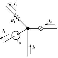
Kirchhoff's circuit laws are two equalities that deal with the current and potential difference in the lumped element model of electrical circuits. They were first described in 1845 by German physicist Gustav Kirchhoff. This generalized the work of Georg Ohm and preceded the work of James Clerk Maxwell. Widely used in electrical engineering, they are also called Kirchhoff's rules or simply Kirchhoff's laws. These laws can be applied in time and frequency domains and form the basis for network analysis.
In power engineering, the power-flow study, or load-flow study, is a numerical analysis of the flow of electric power in an interconnected system. A power-flow study usually uses simplified notations such as a one-line diagram and per-unit system, and focuses on various aspects of AC power parameters, such as voltages, voltage angles, real power and reactive power. It analyzes the power systems in normal steady-state operation.
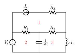
In electrical engineering and electronics, a network is a collection of interconnected components. Network analysis is the process of finding the voltages across, and the currents through, all network components. There are many techniques for calculating these values; however, for the most part, the techniques assume linear components. Except where stated, the methods described in this article are applicable only to linear network analysis.

The asymptotic gain model is a representation of the gain of negative feedback amplifiers given by the asymptotic gain relation:

A magnetic circuit is made up of one or more closed loop paths containing a magnetic flux. The flux is usually generated by permanent magnets or electromagnets and confined to the path by magnetic cores consisting of ferromagnetic materials like iron, although there may be air gaps or other materials in the path. Magnetic circuits are employed to efficiently channel magnetic fields in many devices such as electric motors, generators, transformers, relays, lifting electromagnets, SQUIDs, galvanometers, and magnetic recording heads.
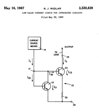
A Widlar current source is a modification of the basic two-transistor current mirror that incorporates an emitter degeneration resistor for only the output transistor, enabling the current source to generate low currents using only moderate resistor values.
In electric circuits analysis, nodal analysis, node-voltage analysis, or the branch current method is a method of determining the voltage between "nodes" in an electrical circuit in terms of the branch currents.
This article illustrates some typical operational amplifier applications. A non-ideal operational amplifier's equivalent circuit has a finite input impedance, a non-zero output impedance, and a finite gain. A real op-amp has a number of non-ideal features as shown in the diagram, but here a simplified schematic notation is used, many details such as device selection and power supply connections are not shown. Operational amplifiers are optimised for use with negative feedback, and this article discusses only negative-feedback applications. When positive feedback is required, a comparator is usually more appropriate. See Comparator applications for further information.
Harmonic balance is a method used to calculate the steady-state response of nonlinear differential equations, and is mostly applied to nonlinear electrical circuits. It is a frequency domain method for calculating the steady state, as opposed to the various time-domain steady-state methods. The name "harmonic balance" is descriptive of the method, which starts with Kirchhoff's Current Law written in the frequency domain and a chosen number of harmonics. A sinusoidal signal applied to a nonlinear component in a system will generate harmonics of the fundamental frequency. Effectively the method assumes a linear combination of sinusoids can represent the solution, then balances current and voltage sinusoids to satisfy Kirchhoff's law. The method is commonly used to simulate circuits which include nonlinear elements, and is most applicable to systems with feedback in which limit cycles occur.

In electronics, a current divider is a simple linear circuit that produces an output current (IX) that is a fraction of its input current (IT). Current division refers to the splitting of current between the branches of the divider. The currents in the various branches of such a circuit will always divide in such a way as to minimize the total energy expended.
A signal-flow graph or signal-flowgraph (SFG), invented by Claude Shannon, but often called a Mason graph after Samuel Jefferson Mason who coined the term, is a specialized flow graph, a directed graph in which nodes represent system variables, and branches represent functional connections between pairs of nodes. Thus, signal-flow graph theory builds on that of directed graphs, which includes as well that of oriented graphs. This mathematical theory of digraphs exists, of course, quite apart from its applications.
The circuit topology of an electronic circuit is the form taken by the network of interconnections of the circuit components. Different specific values or ratings of the components are regarded as being the same topology. Topology is not concerned with the physical layout of components in a circuit, nor with their positions on a circuit diagram; similarly to the mathematical concept of topology, it is only concerned with what connections exist between the components. There may be numerous physical layouts and circuit diagrams that all amount to the same topology.

In electronics, Anderson's bridge is a bridge circuit used to measure the self-inductance of the coil. It enables measurement of inductance by utilizing other circuit components like resistors and capacitors.