Multi-gigabit transceiver

Last updated

A multi-gigabit transceiver (MGT) is a SerDes capable of operating at serial bit rates above 1 Gigabit/second. MGTs are used increasingly for data communications because they can run over longer distances, use fewer wires, and thus have lower costs than parallel interfaces with equivalent data throughput.

Contents

Functions

Like other SerDes, the primary function of the MGT is to transmit parallel data as stream of serial bits, and convert the serial bits it receives to parallel data. The most basic performance metric of an MGT is its serial bit rate, or line rate, which is the number of serial bits it can transmit or receive per second. Although there is no strict rule, MGTs can typically run at line rates of 1 Gigabit/second or more. MGTs have become the 'data highways' for data processing systems that demand a high in/out raw data input and output (e.g. video processing applications). They are becoming very common on FPGA - such programmable logic devices being especially well fitted for parallel data processing algorithms.

Beyond serialization and de-serialization, MGTs must incorporate a number of additional technologies to allow them to operate at high line rates. Some of these are listed below:

TechnologyFunction
Differential signaling MGTs use differential signaling to transmit and receive serial data. Differential signaling allows faster switching, because the change in signal level required to switch from 1 to 0 or 0 to 1 is halved. In addition, as long as the skew between the two lines of each differential pair is minimized, differential signals have increased immunity to Electromagnetic Interference (EMI), crosstalk, and noise.
MOS current mode logic (MCML) MCML refers to current mode logic implemented using MOSFET instead of Bipolar transistors. MCML uses differential amplifiers to drive and receive data at high speeds using low voltages
Emphasis At high line rates, the lines carrying serial data tend to behave like low-pass filters. This causes the high frequency components of the serial data to lose power more quickly than the low frequency components, distorting the signal and causing Intersymbol Interference (ISI). One way to counter this problem is to use Preemphasis or Deemphasis to shape the transmitted signal to compensate for the expected losses.
Receive equalization An alternative to emphasis is Equalization, where the high frequency parts of a received signal's spectrum are amplified more than the low frequency parts, to compensate for the low-pass behavior of the line.
Termination impedance matching At high line rates, the wires used to carry serial data have many of the properties of Transmission lines. One important property is that signals on the line can be distorted if the impedance of the MGT at the transmitter and receiver does not match the impedance of the line. To counter this, MGTs are typically designed to match the impedance of the wires that connect them as closely as possible. A commonly used impedance value is 100Ω (differential, roughly equivalent to 50Ω single ended impedance for each wire).
Phase-locked loops (PLLs) To serialize data at high speeds, the serial clock rate must be an exact multiple of the clock for the parallel data. Most MGTs use a PLL to multiply a reference clock running at the desired parallel rate to the required serial rate.
Clock data recovery (CDR) When serial data are received, the MGT must use the same serial clock that serialized the data to deserialize it. At high line rates, providing the serial clock with a separate wire is very impractical because even the slightest difference in length between the data line and the clock line can cause significant clock skew. Instead, MGTs recover the clock signal from the data directly, using transitions in the data to adjust the rate of their local serial clock so it is locked to the rate used by the other MGT. Systems that use CDR can operate over much longer distances at higher speeds than their non-CDR counterparts.
Encoding/decodingThe pattern of data transmitted serially between MGTs can impact their performance.
  • If the data has too few transitions, the receiving MGT will not be able to use CDR.
  • If the data are too repetitive, at high rates the lines will create strong fields and cause EMI.
  • If the data has too many more 1s than 0s or vice versa, AC coupled MGTs will experience Data Dependent Jitter caused by the charging and discharging of capacitances on the line.

Most communication protocols for MGTs use a data encoding system to avoid these problems.

An additional advantage of encoding is that it allows control information to be transmitted along with data. This is important for functions such as error detection, alignment, clock correction, and channel bonding.

Some popular encodings are:

  • 8b/10b: each octet of data is mapped to a 10-bit sequence
  • 64b/66b: data are grouped into sets of 64 bits, scrambled, then prefixed with a 2-bit header
  • 64b/67b: like 64b/66b, but a 3-bit header is used instead. The extra bit indicates whether the 64 bits are inverted or not, to allow MGTs to ensure the number of 0s and 1s transmitted is roughly balanced
  • SONET/SDH: not an encoding but a group of related standards that group data into fixed size blocks, scramble it, and add a frame which includes an alignment character
Error detectionMost systems require some form of error detection. The most common forms of error detection in MGTs are:
  • Encoding-based error detection: most encodings define a set of legal characters and legal sequences of characters. MGTs can detect errors by looking for data that is illegal in the encoding used.
  • Cyclic redundancy check (CRC): to use CRC, data are broken up into frames (or packets), and a CRC function is applied to each frame. The result of the function is appended to the frame when it is transmitted - the receiver can recalculate the same function on the data it receives and compare it to the result from the transmitter to determine if the data in the frame (or the transmitter's CRC result) was corrupted during transmission.
AlignmentWhen an MGT receives serial data, it needs to determine the byte boundaries of the data before it can present the data as parallel bits. This function is typically performed by an alignment block. The exact method used for alignment depends on the type of encoding used for the data:
  • Comma alignment (8b/10b): the receiver searches the incoming serial stream for commas (8b/10b control characters that cannot be created by concatenating other characters). When it finds a comma, lines up the comma boundary to its byte boundary, so that all the data that follows is aligned.
  • Block synchronization (64b/66b & 64b/67b): the receiver searches the incoming data stream for the 2-bit (or 3-bit, in the case of 64b/67b) header for each 64-bit block.
  • A1/A2 alignment (SONET/SDH): SONET frames include a header and a scrambled payload. MGTs receiving SONET data look for repeated match to the alignment characters in the header (called A1 and A2) to determine byte boundaries.
Clock correctionThere is always a small frequency difference (typically ~+/-100 ppm) between reference clock sources, even if they are nominally the same frequency. As a result, in systems where each MGT uses its own reference clock, each MGT uses a slightly different frequency for its transmit datapath (TX), and its receive datapath (RX).

Many protocols simplify the clocking by using clock correction. In clock correction, each MGT includes an asynchronous FIFO. RX data are written to the FIFO using the serial clock from the CDR, and read from the FIFO using the parallel clock from the rest of the system (the local clock), usually the same parallel clock as was used for TX.

Since the CDR clock and the local clock are not exactly the same, the FIFO will eventually overflow or underflow unless it is corrected. To allow correction, each MGT periodically transmits one or more special characters which the receiver is allowed to remove or replicate in the FIFO as necessary. By removing characters when the FIFO is too full, and replicating characters when the FIFO is too empty, the receiver can prevent overflow/underflow. These special characters are commonly known as SKIP.

Channel bondingMany protocols combine multiple MGT connections to create a single higher throughput channel (e.g. XAUI, PCI Express). Unless each of the serial connections is exactly the same length, skew between the lanes can cause data transmitted at the same time to arrive at different times.

Channel bonding allows the MGTs to compensate for skew between multiple connections. The MGTs all transmit a channel bonding character (or sequence of characters) simultaneously. When the sequence is received, the receiving MGTs can determine the skew between them, then adjust the latency of FIFOs in their receive datapaths to compensate.

Electrical idle/out-of-band signalingSome protocols use the absence of a differential voltage over a specified threshold value to send messages. For example, PCI Express uses Electrical Idle signals to indicate when endpoints should go in and out of low power modes. Similarly, serial ATA uses COM signals for power management. To support these features, MGTs must include circuits capable of generating and detecting electrical idle/OOB signals on the serial lines.

Signal integrity and jitter

Signal integrity is critical for MGTs due to their high line rates. The quality of a given high-speed link is characterized by the bit error ratio (BER) of the connection (the ratio of bits received in error to total bits received), and jitter.

BER and jitter are functions of the entire MGT connection, including the MGTs themselves, their serial lines, their reference clocks, their power supplies, and the digital systems that create and consume their parallel data. As a result, MGTs are often measured by how little jitter they transmit (Jitter Transfer/Jitter Generation), and how much jitter they can tolerate before their BER is too high (Jitter Tolerance). These measurements are commonly taken using a BERT, and analyzed using an eye diagram.

Other considerations

Some other metrics for MGTs include:

Protocols that use MGTs

MGTs are used in the implementation of the following serial protocols:

Related Research Articles

Field-programmable gate array Array of logic gates that are reprogrammable

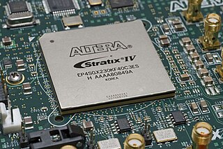
A field-programmable gate array (FPGA) is an integrated circuit designed to be configured by a customer or a designer after manufacturing – hence the term field-programmable. The FPGA configuration is generally specified using a hardware description language (HDL), similar to that used for an application-specific integrated circuit (ASIC). Circuit diagrams were previously used to specify the configuration, but this is increasingly rare due to the advent of electronic design automation tools.

In electronics and telecommunications, jitter is the deviation from true periodicity of a presumably periodic signal, often in relation to a reference clock signal. In clock recovery applications it is called timing jitter. Jitter is a significant, and usually undesired, factor in the design of almost all communications links.

Gigabit Ethernet Standard for Ethernet networking at a data rate of 1 gigabit per second

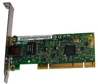
In computer networking, Gigabit Ethernet is the term applied to transmitting Ethernet frames at a rate of a gigabit per second. The most popular variant, 1000BASE-T, is defined by the IEEE 802.3ab standard. It came into use in 1999, and has replaced Fast Ethernet in wired local networks due to its considerable speed improvement over Fast Ethernet, as well as its use of cables and equipment that are widely available, economical, and similar to previous standards.

Small form-factor pluggable transceiver Modular optical fiber communications interface

The small form-factor pluggable (SFP) is a compact, hot-pluggable network interface module used for both telecommunication and data communications applications. An SFP interface on networking hardware is a modular slot for a media-specific transceiver in order to connect a fiber-optic cable or sometimes a copper cable. The advantage of using SFPs compared to fixed interfaces is that individual ports can be equipped with any suitable type of transceiver as needed.

10 Gigabit Attachment Unit Interface is a standard for extending the XGMII between the MAC and PHY layer of 10 Gigabit Ethernet (10GbE) defined in Clause 47 of the IEEE 802.3 standard. The name is a concatenation of the Roman numeral X, meaning ten, and the initials of "Attachment Unit Interface".

The media-independent interface (MII) was originally defined as a standard interface to connect a Fast Ethernet media access control (MAC) block to a PHY chip. The MII is standardized by IEEE 802.3u and connects different types of PHYs to MACs. Being media independent means that different types of PHY devices for connecting to different media can be used without redesigning or replacing the MAC hardware. Thus any MAC may be used with any PHY, independent of the network signal transmission media.

The physical coding sublayer (PCS) is a networking protocol sublayer in the Fast Ethernet, Gigabit Ethernet, and 10 Gigabit Ethernet standards. It resides at the top of the physical layer (PHY), and provides an interface between the Physical Medium Attachment (PMA) sublayer and the media-independent interface (MII). It is responsible for data encoding and decoding, scrambling and descrambling, alignment marker insertion and removal, block and symbol redistribution, and lane block synchronization and deskew.

A Serializer/Deserializer (SerDes) is a pair of functional blocks commonly used in high speed communications to compensate for limited input/output. These blocks convert data between serial data and parallel interfaces in each direction. The term "SerDes" generically refers to interfaces used in various technologies and applications. The primary use of a SerDes is to provide data transmission over a single line or a differential pair in order to minimize the number of I/O pins and interconnects.

Ethernet physical layer Physical network layer of the Ethernet communications technologies

The physical-layer specifications of the Ethernet family of computer network standards are published by the Institute of Electrical and Electronics Engineers (IEEE), which defines the electrical or optical properties and the transfer speed of the physical connection between a device and the network or between network devices. It is complemented by the MAC layer and the logical link layer.

Twinaxial cabling

Twinaxial cabling, or "Twinax", is a type of cable similar to coaxial cable, but with two inner conductors instead of one. Due to cost efficiency it is becoming common in modern (2013) very-short-range high-speed differential signaling applications.

40 Gigabit Ethernet (40GbE) and 100 Gigabit Ethernet (100GbE) are groups of computer networking technologies for transmitting Ethernet frames at rates of 40 and 100 gigabits per second (Gbit/s), respectively. These technologies offer significantly higher speeds than 10 Gigabit Ethernet. The technology was first defined by the IEEE 802.3ba-2010 standard and later by the 802.3bg-2011, 802.3bj-2014, 802.3bm-2015, and 802.3cd-2018 standards.

Camera Link is a serial communication protocol standard designed for camera interface applications based on the National Semiconductor interface Channel-link. It was designed for the purpose of standardizing scientific and industrial video products including cameras, cables and frame grabbers. The standard is maintained and administered by the Automated Imaging Association or AIA, the global machine vision industry's trade group.

QPACE is a massively parallel and scalable supercomputer designed for applications in lattice quantum chromodynamics.

10 Gigabit Ethernet Standards for Ethernet at ten times the speed of Gigabit Ethernet

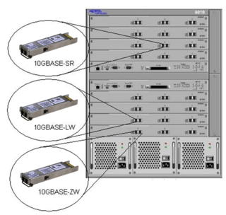
10 Gigabit Ethernet is a group of computer networking technologies for transmitting Ethernet frames at a rate of 10 gigabits per second. It was first defined by the IEEE 802.3ae-2002 standard. Unlike previous Ethernet standards, 10 Gigabit Ethernet defines only full-duplex point-to-point links which are generally connected by network switches; shared-medium CSMA/CD operation has not been carried over from the previous generations Ethernet standards so half-duplex operation and repeater hubs do not exist in 10GbE.

Terabit Ethernet or TbE is Ethernet with speeds above 100 Gigabit Ethernet. 400 Gigabit Ethernet and 200 Gigabit Ethernet standards developed by the IEEE P802.3bs Task Force using broadly similar technology to 100 Gigabit Ethernet were approved on December 6, 2017. In 2016, several networking equipment suppliers were already offering proprietary solutions for 200G and 400G.

25 Gigabit Ethernet and 50 Gigabit Ethernet are standards for Ethernet connectivity in a datacenter environment, developed by IEEE 802.3 task forces 802.3by and 802.3cd and are available from multiple vendors.

In computing, a logic block or configurable logic block (CLB) is a fundamental building block of field-programmable gate array (FPGA) technology. Logic blocks can be configured by the engineer to provide reconfigurable logic gates.

IEEE 802.3bz, NBASE-T and MGBASE-T are standards for Ethernet over twisted pair at speeds of 2.5 and 5 Gbit/s. These use the same cabling as the ubiquitous Gigabit Ethernet, yet offer higher speeds. The resulting standards are named 2.5GBASE-T and 5GBASE-T.

An optical module is a typically hot-pluggable optical transceiver used in high-bandwidth data communications applications. Optical modules typically have an electrical interface on the side that connects to the inside of the system and an optical interface on the side that connects to the outside world through a fiber optic cable. The form factor and electrical interface are often specified by an interested group using a multi-source agreement (MSA). Optical modules can either plug into a front panel socket or an on-board socket. Sometimes the optical module is replaced by an electrical interface module that implements either an active or passive electrical connection to the outside world. A large industry supports the manufacturing and use of optical modules.

References