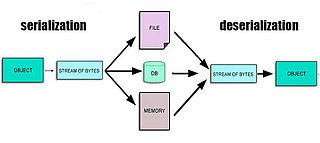
In computing, serialization is the process of translating a data structure or object state into a format that can be stored or transmitted and reconstructed later. When the resulting series of bits is reread according to the serialization format, it can be used to create a semantically identical clone of the original object. For many complex objects, such as those that make extensive use of references, this process is not straightforward. Serialization of objects does not include any of their associated methods with which they were previously linked.
In telecommunications, a line code is a pattern of voltage, current, or photons used to represent digital data transmitted down a communication channel or written to a storage medium. This repertoire of signals is usually called a constrained code in data storage systems. Some signals are more prone to error than others as the physics of the communication channel or storage medium constrains the repertoire of signals that can be used reliably.
A shift register is a type of digital circuit using a cascade of flip-flops where the output of one flip-flop is connected to the input of the next. They share a single clock signal, which causes the data stored in the system to shift from one location to the next. By connecting the last flip-flop back to the first, the data can cycle within the shifters for extended periods, and in this configuration they were used as computer memory, displacing delay-line memory systems in the late 1960s and early 1970s.

Digital Visual Interface (DVI) is a video display interface developed by the Digital Display Working Group (DDWG). The digital interface is used to connect a video source, such as a video display controller, to a display device, such as a computer monitor. It was developed with the intention of creating an industry standard for the transfer of uncompressed digital video content.

Low-voltage differential signaling (LVDS), also known as TIA/EIA-644, is a technical standard that specifies electrical characteristics of a differential, serial signaling standard. LVDS operates at low power and can run at very high speeds using inexpensive twisted-pair copper cables. LVDS is a physical layer specification only; many data communication standards and applications use it and add a data link layer as defined in the OSI model on top of it.

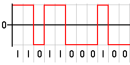
In telecommunication and data transmission, serial communication is the process of sending data one bit at a time, sequentially, over a communication channel or computer bus. This is in contrast to parallel communication, where several bits are sent as a whole, on a link with several parallel channels.
In telecommunications and electronics, a self-clocking signal is one that can be decoded without the need for a separate clock signal or other source of synchronization. This is usually done by including embedded synchronization information within the signal, and adding constraints on the coding of the data payload such that false synchronization can easily be detected.
In telecommunications, 8b/10b is a line code that maps 8-bit words to 10-bit symbols to achieve DC balance and bounded disparity, and at the same time provide enough state changes to allow reasonable clock recovery. This means that the difference between the counts of ones and zeros in a string of at least 20 bits is no more than two, and that there are not more than five ones or zeros in a row. This helps to reduce the demand for the lower bandwidth limit of the channel necessary to transfer the signal.

Transition-minimized differential signaling (TMDS) is a technology for transmitting high-speed serial data used by the DVI and HDMI video interfaces, as well as by other digital communication interfaces.
10 Gigabit Attachment Unit Interface is a standard for extending the XGMII between the MAC and PHY layer of 10 Gigabit Ethernet (10GbE) defined in Clause 47 of the IEEE 802.3 standard. The name is a concatenation of the Roman numeral X, meaning ten, and the initials of "Attachment Unit Interface".
The media-independent interface (MII) was originally defined as a standard interface to connect a Fast Ethernet medium access control (MAC) block to a PHY chip. The MII is standardized by IEEE 802.3u and connects different types of PHYs to MACs. Being media independent means that different types of PHY devices for connecting to different media can be used without redesigning or replacing the MAC hardware. Thus any MAC may be used with any PHY, independent of the network signal transmission medium.
The physical coding sublayer (PCS) is a networking protocol sublayer in the Fast Ethernet, Gigabit Ethernet, and 10 Gigabit Ethernet standards. It resides at the top of the physical layer (PHY), and provides an interface between the physical medium attachment (PMA) sublayer and the media-independent interface (MII). It is responsible for data encoding and decoding, scrambling and descrambling, alignment marker insertion and removal, block and symbol redistribution, and lane block synchronization and deskew.
In telecommunications, 6b/8b is a line code that expands 6-bit codes to 8-bit symbols for the purposes of maintaining DC-balance in a communications system.
In serial communication of digital data, clock recovery is the process of extracting timing information from a serial data stream itself, allowing the timing of the data in the stream to be accurately determined without separate clock information. It is widely used in data communications; the similar concept used in analog systems like color television is known as carrier recovery.
In data networking and transmission, 64b/66b is a line code that transforms 64-bit data to 66-bit line code to provide enough state changes to allow reasonable clock recovery and alignment of the data stream at the receiver. It was defined by the IEEE 802.3 working group as part of the IEEE 802.3ae-2002 amendment which introduced 10 Gbit/s Ethernet. At the time 64b/66b was deployed, it allowed 10 Gb Ethernet to be transmitted with the same lasers used by SONET OC-192, rather than requiring the 12.5 Gbit/s lasers that were not expected to be available for several years.
A Multichannel Audio Serial Port (McASP) is a communication peripheral in digital signal processor (DSP) and microcontroller unit (MCU) components from Texas Instruments.
A multi-gigabit transceiver (MGT) is a SerDes capable of operating at serial bit rates above 1 Gigabit/second. MGTs are used increasingly for data communications because they can run over longer distances, use fewer wires, and thus have lower costs than parallel interfaces with equivalent data throughput.
The Aurora Protocol is a link layer communications protocol for use on point-to-point serial links. Developed by Xilinx, it is intended for use in high-speed connections internally in a computer or in an embedded system. It uses either 8b/10b encoding or 64b/66b encoding.
ARINC 818: Avionics Digital Video Bus (ADVB) is a video interface and protocol standard developed for high bandwidth, low-latency, uncompressed digital video transmission in avionics systems. The standard, which was released in January 2007, has been advanced by ARINC and the aerospace community to meet the stringent needs of high performance digital video. The specification was updated and ARINC 818-2 was released in December 2013, adding a number of new features, including link rates up to 32X fibre channel rates, channel-bonding, switching, field sequential color, bi-directional control and data-only links.
