In building wiring, multiway switching is the interconnection of two or more electrical switches to control an electrical load from more than one location. A common application is in lighting, where it allows the control of lamps from multiple locations, for example in a hallway, stairwell, or large room.
In contrast to a simple light switch, which is a single pole, single throw (SPST) switch, multiway switching uses switches with one or more additional contacts and two or more wires are run between the switches. When the load is controlled from only two points, single pole, double throw (SPDT) switches are used. Double pole, double throw (DPDT) switches allow control from three or more locations.
In alternative designs, low-voltage relay or electronic controls can be used to switch electrical loads, sometimes without the extra power wires.
Three-way and four-way switches
A double pole, double throw switch wired to act as a four-way (intermediate or crossover) switch
This article follows usage in the United States. Readers in most other countries should read "two-way" or "SPDT" for the United States "three-way"; and "intermediate", "crossover" or "DPDT" switch for the United States "four-way".
The controlled load is often a lamp, but multiway switching is used to control other electrical loads, such as an electrical outlet, fans, pumps, heaters or other appliances. The electrical load may be permanently hard-wired, or plugged into a switched receptacle.
Three-way and four-way switches make it possible to control a light from multiple locations, such as the top and bottom of a stairway, either end of a long hallway, or multiple doorways into a large room. These switches appear externally similar to single pole, single throw (SPST) switches, but have extra connections which allow a circuit to be controlled from multiple locations. Toggling the switch disconnects one "traveler" terminal and connects the other.
Electrically, a typical "3-way" switch is a single pole, double throw (SPDT) switch. By correctly connecting two of these switches together, toggling either switch changes the state of the load from off to on, or vice versa. The switches may be arranged so that they are in the same orientation for off, and contrasting orientations for on.[citation needed]
A "4-way" (intermediate) switch is a purpose built double pole, double throw (DPDT) switch, internally wired in manufacture to reverse the connections between the input and output and having only four external terminals. This switch has two pairs of "traveler" terminals that it connects either straight through, or crossed over (transposed, or swapped). An intermediate switch can, however, be implemented by adding appropriate external wiring to an ordinary (six-terminal) DPDT switch, or by using a separate DPDT relay.
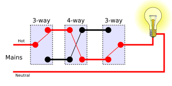
By connecting one or more 4-way (intermediate) switches in-line, with 3-way switches at either end, the load can be controlled from three or more locations. Toggling any switch changes the state of the load from off to on, or from on to off.
Two locations
Switching a load on or off from two locations (for instance, turning a light on or off from either end of a flight of stairs) requires two SPDT switches. There are several arrangements of wiring to achieve this.
Traveler system
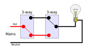
In the traveler system, also called the "common" system, the power line (hot, shown in red) is fed into the common terminal of one of the switches. The switches are then connected to each other by a pair of wires called "travelers" (or "strappers" in the UK), and the lamp is connected to the common terminal of the second switch, as shown.
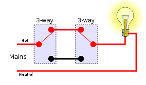
Using the traveler system, there are four possible permutations of switch positions: two with the light on and two with the light off.
Off
On
Alternative system
An alternative system, known as the "California 3-way", or "coast 3-way" connection system allows both switched and unswitched loads to be connected near both switches without running too many additional wires. This is useful in long hallways that may need more than one light to be controlled by the two switches, and which may also have receptacles needing unswitched power as well as the switched lights. If only one light is being switched and no unswitched connection is needed, this system uses more long wires than the standard system (four instead of three), but if the switched light is close to the switch near the fuse box and a receptacle needs to be powered near the far switch it will use fewer long wires (four instead of five).
The "California 3-way" or "Coast 3-way" connection also never connects the lamp socket shell to the line (hot) terminal. An optional additional lamp can be connected at Terminal A as a pilot lamp, or to illuminate a long corridor. An optional receptacle can be connected at Terminal B, since that terminal is always live.
Comparison of the traveler (1) and California 3-way (2) systems with multiple switched and unswitched lights
Neutral required
Since the 2020 edition of the United States National Electrical Code, in Article 404, the circuit neutral conductor is required to be present in every box containing a switch that controls the light circuit. A circuit neutral is necessary for timer or remote control switching devices that require a neutral connection. Alternatives to the standard wiring system may not provide a circuit neutral and so would not be acceptable in installations covered by recent editions of the NEC.[1]
An exception is made in Article 404(A)(1.2.3) stating:
"Where multiple switch locations control the same lighting load such that the entire floor area of the room or space is visible from the single or combined switch locations, the grounded circuit conductor shall only be required at one location."[2]
Installations of California 3-way wiring providing a neutral wire in one of the two switch locations would still be code compliant in this situation. The idea is that the smart switch can be installed in the location with the neutral, while the add-on (passive) switch in the pair does not require a neutral to function.
Carter system
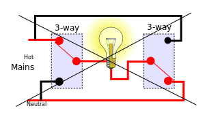
The Carter system is prohibited in the US
The Carter system, also known as the Chicago system, was a method of wiring three-way switches in the era of early knob-and-tube wiring. This now-obsolete wiring method has been prohibited by the United States National Electrical Code since 1923,[3] even in new knob-and-tube installations which are still permitted under certain circumstances. This wiring system may still be encountered in old "grandfathered" electrical installations.
In the Carter system, the incoming live (energized) and neutral wires were connected to the traveler screws of both three-way switches, and the lamp was connected between the common screws of the two switches. If both switches were flipped to hot or both were flipped to neutral, the light would remain off; but if they were switched to opposite positions, the light would illuminate. The advantage of this method was that it used just one wire to the light from each switch, having a hot and neutral in both switches.
The major problem with this method is that in two of the four switch combinations, the shell of the socket is energized, creating a risk of electrical shock hazard for anyone replacing the bulb. In one of the combinations with the lamp off, the socket is electrified at both of its terminals. In one of the combinations with the bulb on, the bulb is powered "backwards", with a grounded center connector and an energized shell, meaning that a burnt-out bulb similarly has an electrified shell. This method is therefore prohibited in modern building wiring where Edison screw-based lamps are used.
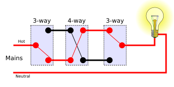
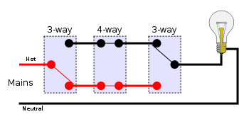
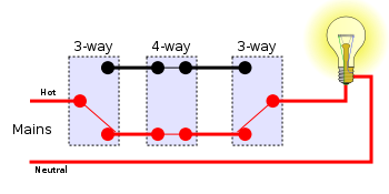
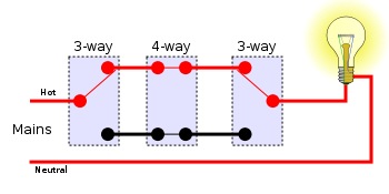
More than two locations
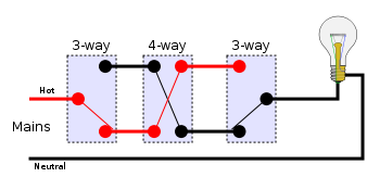
For more than two locations, two of the interconnecting wires must be passed through an intermediate switch, wired to swap or transpose the pair. Any number of intermediate switches can be inserted, allowing for any number of locations. This requires two wires along the sequence of switches.
Traveler system
Using three switches, there are eight possible permutations of switch positions: four with the light on and four with the light off. (These diagrams also use the American electrical wiring names.)
Off
On
As mentioned above, the above circuit can be extended by using multiple 4-way switches between the 3-way switches to extend switching ability to any number of locations.
Four sample arrangements
Low-voltage relay switching
Systems based on relays with low-voltage control circuits permit switching the power to lighting loads from an arbitrary number of locations. For each load, a latching relay is used that mechanically maintains its on- or off-state, even if power to the building is interrupted. Mains power is wired through the relay to the load.
Instead of running mains voltage to the switches, a low voltage—typically 24 V AC—is connected to remote momentary toggle or rocker switches. The momentary switches usually have SPDT contacts in an (ON)-OFF-(ON) configuration. Pushing the switch actuator in one direction causes the relay contacts to close; pushing it in the opposite direction causes the relay contacts to open. Any number of additional rocker switches can be wired in parallel, as needed, in multiple locations. An optional master control can be added that turns all lights in the facility on or off simultaneously under the control of a timer or computer.
After an initial burst of popularity in the 1960s, residential use of such relay-based low-voltage systems has become rare. Equipment for new installations is not commonly carried by electrical suppliers, although it is still possible to find parts for maintaining existing installations.
As of 2012,[update] multiway switching in residential and commercial applications is increasingly being implemented with power-line signalling and wireless signalling techniques. These include the X10 system, available since the 1970s, and newer hybrid wired/wireless systems, such as Insteon and Z-Wave. This is particularly useful when retrofitting multi-way circuits into existing wiring, often avoiding the need to put holes in walls to run new wires.
Remote-control systems are increasingly used in commercial buildings as part of lighting systems under semi-automatic control, for better safety, security, and energy conservation.
↑ NEC Article 404.2 Switch Connections: (A) ... Three-way and four-way switches shall be wired so that all switching is done only in the ungrounded circuit conductor ... (B) Grounded Conductors. Switches or circuit breakers shall not disconnect the grounded conductor of a circuit. Switching a neutral is generally forbidden by the NEC unless the hot conductor is opened simultaneously
Day, Richard (January 1987). "Wiring Multi Switches". Popular Science. 230 (1): 85–. ISSN0161-7370.
Litchfield, Michael & McAlister, Michael (2008). Taunton's Wiring Complete: Expert Advice from Start to Finish (reviseded.). Newtown, Connecticut: Taunton Press. ISBN9781600852565.
This page is based on this Wikipedia article Text is available under the CC BY-SA 4.0 license; additional terms may apply. Images, videos and audio are available under their respective licenses.