This article is about plugboards, or control panels, in unit record machines, cypher machines and early computers. For other uses, see Plug board.
IBM 402 accounting machine control panel wiring. This board was labeled "profit & loss summary."Reverse side of the same 402 plugboard, showing the pins that make contact with the machine's internal wiring. The holes were called hubs.
A plugboard or control panel (the term used depends on the application area) is an array of jacks or sockets (often called hubs) into which patch cords can be inserted to complete an electrical circuit. Control panels are sometimes used to direct the operation of unit record equipment, cipher machines, and early computers. The array of holes is often contained in a flat removable panel that can be inserted into a machine and pressed against an array of contacts. This allows the machine to be quickly switched between different applications.
The contacts on the machine are hard wired to the various devices that comprise the machine, such as relays, counters, inputs from each card reader column, outputs to a card punch column or printer position, and so on. The wiring on a plugboard connects these devices to perform a specific function, say reading cards and summing up the numbers punched in a group of columns. A modern comparison would be a field-programmable gate array (FPGA), with the plugboard serving the same purpose as the wiring layer in the FPGA.
An operator inserting a control panel into an IBM 407 Accounting Machine Another panel is on the floor nearby.
The earliest machines were hardwired for specific applications. Inspired by telephone switchboards, Otto Schäffler invented the plugboard in order to easily reprogram tabulators.[3][4] Applications then could be wired on separate control panels, and inserted into tabulators as needed. Removable control panels came to be used in all unit record machines where the machine's use for different applications required rewiring.
IBM removable control panels ranged in size from 6 1/4" by 10 3/4" (for machines such as the IBM 077, IBM 550, IBM 514) to roughly one to two feet (300 to 600mm) on a side and had a rectangular array of hubs.[5]Plugs at each end of a single-conductor patch cord were inserted into hubs, making a connection between two contacts on the machine when the control panel was placed in the machine, thereby connecting an emitting hub to an accepting or entry hub. For example, in a card duplicator application a card column reading (emitting) hub might be connected to a punch magnet entry hub. It was a relatively simple matter to copy some fields, perhaps to different columns, and ignore other columns by suitable wiring. Tabulator control panels could require dozens of patch cords for some applications.
Tabulator functions were implemented with both mechanical and electrical components. Control panels simplified the changing of electrical connections for different applications, but changing most tabulator's use still required mechanical changes. The IBM 407 was the first IBM tabulator that did not require such mechanical changes; all the 407's functions were electrically controlled and were completely specified by the application's control panel and carriage tape.
For most machines with control panels, from collators, interpreters, to the IBM 407, IBM manuals describe the control panel as "directing" or "automatic operation was obtained by...". The control panels of calculators, such as the IBM 602 and IBM 604, that specified a sequence of operations, were described as being programs.
Wiring of unit record equipment control panels
An 80-column punched card. Rows 0 to 9 are labeled. The 12 row, on top, has one punch in column 7. The 11 row, below it is not punched on this card. As cards passed through a read station, usually 9-edge (bottom edge) first, wire brushes, one for each column, would make contact through the holes.Relays, such as this, were widely used in unit record equipment. When current flows through electromagnet, 1, the iron armature, 2, is pulled in, pivoting on a bearing at its corner (not shown) to move the common contact, 3. A relay can have more than one set of contacts. Co-selector relays had five sets.
Unit record equipment was typically configured for a specific task using a removable control panel. The electrical connections of the various components in the unit record machine were presented on the panel, and connections between them were determined by the wiring, with the actual connections made when the panel was inserted into the machine and locked in place. Perhaps the closest modern analog is the field-programmable gate array, where a fixed number of logic components are made available and their interconnection wiring is determined by the user.
Wiring a unit record control panel required knowledge of the machine's components and their timing constraints. The components of most unit record machines were synchronized to a rotating shaft. One rotation represented a single machine cycle, during which punched cards would advance from one station to the next, a line might be printed, a total might be printed and so on. The cycles were divided into points according to when the rows on a punched card would appear under a read or punch station. On most[6] machines, cards were fed face down, 9-edge (bottom edge) first. Thus the first point in a card cycle would 9-time, the second 8 time and so on to 0-time. The times from 9 to 0 were known as digits. These would be followed by 11 time and 12 time, also known as zones.
In a read station, a set of 80 spring wire brushes pressed against the card, one for each column (the 407 read station, constructed without brushes, held the card stationary and could read a card multiple times, each time generating the same impulses as would be generated by an 80 spring wire station). When a hole passed under the brush, the brush would make contact with a conductive surface beneath the card that was connected to an electrical power source and an electrical pulse, an impulse in IBM terminology, would be generated. Each brush was connected to an individual hub on the control panel, from which it could be wired to another hub, as needed. The action caused by an impulse on a wire depended on when in the cycle it occurred, a simple form of time-division multiplexing. Thus an impulse that occurred during 7-time on a wire connected to the column 26 punch magnet would punch a hole in row 7 of column 26. An impulse on the same wire that occurred at 4-time would punch a 4 in column 26. Impulses timed in this way often came from read brushes that detected holes punched in cards as they passed under the brushes, but such pulses were also emitted by other circuits, such as counter outputs. Zone impulses and digit impulses were both needed for alphanumeric printing. They could both be sent on a single wire, then separated out by relay circuits based on the time within a cycle.
The control panel for each machine type presented exit (output) and entry (input) hubs in logical arrangements. In many places, two or more adjacent common hubs, would be connected, allowing more than one wire to be connected to that exit or entry. A few groups of hubs were wired together but not connected to any internal circuits. These bus hubs could be used to connect multiple wires when needed. Small connector blocks called wire splits were also available to join three or four wires together, above the control panel. Several are visible in the photo of an IBM 402 panel.
The capabilities and sophistication of unit record machine components evolved over the first half of the 20th century and were often specific to the needs of a particular machine type. The following hub groupings were typical of later IBM machines:[7]
Read brushes, 80 exit hubs, one for each card column. A tabulating machine might have two or three read stations, each with its own set of 80 hubs. A reproducing punch might have an additional read station after the punch station for verification.
Punch magnets Machines that could punch cards, such as a reproducing punch, had hub entries for each card column. An impulse to one of those entries triggered the electromagnet that initiated the punching of a hole at that column position.
Print entries, one hub for each print position. Impulses to these entries controlled the motion of print bars or wheels to place the correct type element under the print hammers. The 407 also had exits from each print wheel that could then feed the counters for addition or subtraction. This insured that totals always matched what was printed.
Counter entries. An IBM tabulating machine, such as the 402 or 407 series would have several counters available in different sizes. (For example, the IBM 402/403 had four sets each of 2, 4, 6 and 8 digit counters, labeled 2A, 2B, 2C, 2D, 4A, 4B etc.) Each counter had two counter control entries to specify either addition (plus) or subtraction (minus). If neither were pulsed, no operation was performed. If addition was commanded, a digit impulse wired from a column to a counter entry hub started the counter wheel turning. It stopped automatically at zero time. Thus a pulse at 8 time caused the wheel to advance 8 steps, adding the value 8 to that counter position. Carries within a group were performed automatically. Carry in and carry out hubs allowed counters to be coupled, permitting longer numbers to be accumulated. Subtraction was more complicated and used nines complement arithmetic.
Counter total exits. A counter's Total entry hub caused that counter to emit total pulses which could be wired to print positions. After a total was printed, the counter was reset. Special circuits allowed negative values to be printed correctly, not as nines complements, and a special exit was provided to allow an appropriate symbol ("cr" or "-") to be printed next to the number when it was negative.
Comparing. Simple comparing circuits had two entries and one exit that emitted a pulse whenever pulses arrived at the entries at different times. Some machines, e.g. collators, could detect which number was higher if they were not equal. A tabulating machine might compare the account number on successive cards and print a total when a new account number appeared. For the compare function, IBM implemented what would now be called a XOR gate using opposing electromagnets. If neither magnet was energized or both magnets were energized at the same time, the relay armature would not move. If only one magnet was energized, the armature would move and touch one of two contacts placed on either side. The two contacts were wired together internally and connected to an exit hub that indicated an unequal comparison.
Distributors allowed an output pulse to be wired to more than one input without creating a back circuit between the inputs.
Emitters were sets of 12 exit hubs that automatically generated a pulse at each specified time in the card cycle. The twelve exit hubs were wired to contacts on a rotary switch that turned with the card cycle. Thus wiring the 6 exit from an emitter to a punch magnet entry would cause a 6 to be punched at that position. Emitters might be used to put a numeric constant value, say a date, on every card. Alphanumeric constant data could be created by carefully combining digit and zone pulses. Later machines, such as the 407 also had a complete set of alphanumeric emitters that only required one wire to use.
Selectors directed a pulse from a common entry to either of two outputs, depending on whether a relay magnet was energized. Many types of selectors were employed that differed in how the "pickup" relay was energized. In the simplest case, immediate (I) entries, the magnet was energized when a pulse was received and held for the remainder of the cycle. More complex selectors, called pilot selectors, had a D entry hub that caused the selector magnet to pick up on the next machine cycle, and X entry hub that also delayed but was only triggered by an 11 or 12 pulse. The one-cycle delay was needed because in most cases, by the time a pulse was detected it was too late to reliably take action in that cycle. Co-selectors had only an immediate input, but five sets of contacts and were typically triggered by a pilot selector's coupling exit, hence the names.
Digit selectors were similar to emitters, with one exit hub for each cycle point, but they also had an entry hub that was switched to the successive exit hubs as the cycle progressed. A digit selector could be converted to a digit emitter by wiring its entry hub to a constant source of cycle pulses. But it could also be fed other signals and used to detect a particular digit. Wiring a first read brush to a digit selector's entry and connecting, say, its 4 exit to a pilot selector's D entry would cause that selector to transfer on the next read cycle if a 4 was punched in that first read brush's column.
Column splits were relays that energized during only at 11 and 12-time, allowing digit pulses to be separated from zone pulses.
Storage. Later machines such as the 407 and 602 could store several values for later use, by means of a mechanical device somewhat similar to an emitter, except it contained a sliding contact that determined at what time point an impulse was to be emitted. The contact slider was positioned electro-mechanically when a value was stored, and stayed in position until the storage was cleared.
Cypher machines
The plugboard (steckerbrett) on the Enigma is positioned at the front of the machine, below the keys. In the photograph, two pairs of letters are swapped (S-O and J-A). Up to 13 letters can be swapped this way.
A plugboard was used on the famous Enigma machine; it was not removable. In this case the plugboard acted as a "fourth rotor" in the rotor machine's workings. Plugboard wirings were part of the "day settings" that specified which rotors to insert into which slot, and which plugboard connections to make. In practice the plugboard did improve the security of the cypher being generated, but as it did not change with every keypress, unlike the rotors, its impact was limited. SeeCryptanalysis of the Enigma.
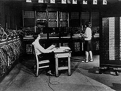
Early computers
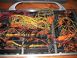
ENIAC wiring panels
The first version of the ENIAC computer was programmed via cabling, switches and plugboards. ENIAC's cabling was later reconfigured to use the existing Function Tables data ROM memory as program ROM memory (the switches and plugboards continued to be used in the reconfigured ENIAC).
The IBM 305 RAMAC used a plugboard for all program compare operations and all branch operations. Other plugboards controlled card reading and punching, the printer and the console typewriter.[8] Many peripheral devices, e.g. the IBM 711 and 716, for first and second generation IBM computers, including the IBM 700/7000 series and the IBM 650, were based on unit record machines and included plugboards.
Plugboards remained in use in specialty-purpose computers for some time, acting as a read only memory (ROM) but able to be manually reprogrammed in the field. One example is the Ferranti Argus computer, used on the Bristol Bloodhound missile, which feature a plugboard programmed by inserting small ferrite rods into slots, in effect creating a read-only core memory by hand.
↑ Early IBM removable control panels had an array of sockets on one side, each socket wired to a connector on the reverse side. As the function of such panels is identical to the later control panels with hubs, this article uses only the hub terminology.
↑ Note: A major exception were reproducers (514...) and interpreters (552 ...), which took cards 12 edge (top edge) first.
Brooks Jr., Frederick P.; Iverson, Kenneth E. (1963) Automatic Data Processing, Wiley, 494pp. Well written descriptions of unit record machines and control panel wiring, both IBM and Remington Rand.
External links
Wikimedia Commons has media related to plugboards.
This page is based on this Wikipedia article Text is available under the CC BY-SA 4.0 license; additional terms may apply. Images, videos and audio are available under their respective licenses.