Statements like those in AS3850, "Because of the mode in which failure can occur, it may be necessary to test complete systems and not calculate values obtained from a group of components that make up the system. The mode of failure of an individual component does not necessarily reflect the mode of failure of the system." But the standard does not continue to further the understanding required regarding test methods, the components that should be deemed as part of the system, the various modes of failure, and the interpretation of test results for each failure mode.
And further in AS3850, "The strength limit state capacity shall be determined by a statistical analysis from the test results in accordance with Paragraph A4.5." and assuming the test data is taken from a statistically valid test method, the data is to be determined via statistical means to derive the Load resistance model, for the anchor.
Fig 1: Load resistance elements of an anchor system in a wall panel
Fig 2: Lifting system model for a thin section wall panel
The rigging arrangements can influence the applied anchor load, where statically indeterminate systems are not necessarily a design consideration, but can be used in practice. The determination of the loads through the rigging system must be a consideration whilst calculating the load resistant model, refer to the examples shown in Figure 3.
Basic principles
Even though years of experience accounts for a good gauge for the appropriate lifting anchor to be used, it should not be left to the reinforcement fabricators and precast factory personnel to select the lifting anchor. The design engineer should specifically account for the applied loads expected during the lifting, transport and placement (or re-usability requirements) of the element. Flexure, casting bed suction, load direction (axial 'tensile', angular 'sling', transverse 'shear') are also load considerations to be accounted for in the lifting design of the element.
The anchor selection, together with additional reinforcement, and rigging arrangements is influenced by:
The dead weight of the element
The number of anchors in the element and the configuration of the anchor.
Capacity of the anchor at the specific concrete compressive strengths at time of lift. The dynamic loads applied during lifting (suction to the casting bed, or crane dynamics)
The rigging configuration. All of the above factors must be taken into consideration during the lifting design phase of the element. The weight of the element can be determined by the calculated volume, and using the specific gravity (normal weight reinforced concrete is approximately 24kN/m3).
Establishing the lifting anchor positions will influence the rigging arrangements used and therefore the static analysis of the rigging should be determined. Particular rigging configurations may be more suitable for particular job sites or lifting in place considerations, and the lifting design should denote the assumptions accordingly. For example, the statically determined systems, shown in Figure 3, where the determination of the loads is not always possible.
Fig 3: Rigging configurations determining load sharing per anchor
Dynamic loads considered in lifting design are accounted for in two stages; suction to the casting bed on the initial lift and then the dynamic loads induced from crane vibration. These crane impact loads must be accounted for during transportation in the yard and on-site, and the coefficient increases from an overhead gantry crane through to a crane moving over rough terrain. Consideration for the entire transportation loads must be taken into account during the lifting design.
Anchor capacity, or load resistance, should be considered for tensile loads (axial), sling angle (angular) and shear loads (transverse). Consideration of different load combinations may result in wide variations required from the lifting insert. The load directions during production, transport and placement should be considered carefully. Depending on the planned load direction, either a different anchor may be included in the lifting design, alternatively, reinforcement may be included to reduce the possibility of element flexure crack damage. The configuration (size, position and quantity) of this reinforcement should be supplemented to the element reinforcement design to ensure for adequate capacity of the lifting design.
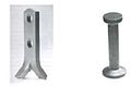
Lifting design is influenced by the steel / concrete interaction of the specific anchor selected. Different load cases are considered by the lifting design engineer, such as anchor susceptibility to edge distance, placement sensitivity, and anchor capacity at the specific concrete strength at time of lift. For example, a footed pin head style anchor maybe more susceptible to edge distance than a hairpin style anchor. Or a splayed anchor does not have the same tensile/axial capacity with the equivalent anchor length (effective embedment is greater on a footed anchor than a splayed anchor of equivalent overall length, see figure 4).
Fig 4: These 2 anchors may have the same overall length, but very different Effective Embedment Depths, hef
Fig 5: These 2 anchors have different concrete load interactions, where the footed anchor is more susceptible to side blow-out in thin wall sections
Examples
Practical application must consider that the Load Resistance ≥ Applied Load
To determine the required anchor, the manufacturing plant handling and the site handling should be considered separately.
Example: A thin walled rectangular section, 6.0 m long, 3.0 m wide and 150mm thick is being considered to be edge lifted from a horizontal steel bed using an overhead gantry crane, and then lifted on-site using a tower crane. No panel rotation is being considered.
Panel
Volume: V = w x h x d = 6.0 m x 3.0 m x 0.15 m = 2.7 m3
Weight: W = V x concrete specific gravity = 2.7 m3 x 24kN/m3 = 64.8kN
Calculated casting bed suction
Suction area: A = w x h = 6.0 m x 3.0 m = 18 m2
Assuming 1.0kN/m2 is applied for oiled steel formwork
Suction force: S = A x 1.0kN/m2 = 18 x 1.0 = 18kN
Applied loads at element lifting (sling angle and lateral tension)
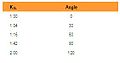
F = W x Ksl x Ks x 0.5 = 64.8 x 1.16 x 1.2 x 0.5 = 45.1kN
Anchor capacity for initial lift
F/n = 23kN per anchor during initial lift (n = 2 lifting anchors)
Transport loads in the yard and on-site
Suction due to casting bed adhesion is not considered, as the calculation takes into account the lifting device dynamic coefficient.
S = (W x Ksl x Kd) / n = (64.8 x 1.16 x 1.2) / 2 = 45.1kN load resistance required per anchor
Anchor capacity for site lift
F/n = 23kN per anchor during site lifting (n = 2 lifting anchors)
Reference to the load capacity tables provided by the anchor manufacturer is required to make an anchor selection for the specific concrete strengths at the time of lifting. Hence the great of the two calculated anchor capacities required at the concrete strength of the initial lift is normally selected.
Anchor interactions
When selecting an anchor, consider the element formwork and the ease of placement and securing of the anchor prior and during the pouring of the concrete. For example, some of the anchors shown in figures 4-6, can be placed into thin wall elements as the anchor chair maintains the position relative to the element thickness. As the orientation of the void determines the lift position of the lifting clutch, the wire chair can be secured against the element reinforcement to maintain this orientation during the concrete pour and set.
When an anchors load resistance must consider load reduction factors, this would imply that the particular selected anchor will form a different failure crack zone. For example, the anchors depicted in figure 5, a footed anchor has the tendency to overload the concrete cover in thin wall panels, hence is more susceptible to side blow-out failure than a hairpin style anchor, depicted in figure 8.
Fig 6: Typical Tilt-up facelift systems – thin wall panels or thin section elements required to be face lifted
Figure 7: Typical general element systems – facelift anchors normally placed in general precast elements
Figure 8: Typical edgelift systems – used for the majority of wall panel edgelifting
Conclusion
Lifting design if done correctly will consider many aspects which should be considered through the transportation load cycle of the concrete element. The considerations should cover the lifting system model and load resistance model. Using suitably qualified and experienced engineers is certainly recommended as the consequences of getting the lifting design incorrect can be fatal.
Efficiencies can be gained from getting the lifting design correct, by optimizing the number of anchors, correct reinforcement detail of the element, the correct selection of the anchor type and the minimizing the complexities of the rigging configurations.[1]
[1] Prestressed Concrete Institute (PCI). PCI design handbook. 6th edition Chicago (IL): Precast/Prestressed Concrete Institute; 2004.
[2] Australian Standards 3600 (AS). Concrete Structures (AS3600-2009), Sydney Australia, Standards Australia; 2009
[3] Australian Standards 3850 (AS). Tilt-up concrete construction (AS3850-2003), Sydney Australia, Standards Australia; 2003
This page is based on this Wikipedia article Text is available under the CC BY-SA 4.0 license; additional terms may apply. Images, videos and audio are available under their respective licenses.