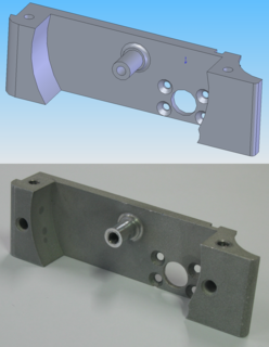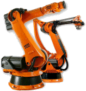
Computer-aided manufacturing (CAM) also known as Computer-aided Modeling or Computer-aided Machining is the use of software to control machine tools and related ones in the manufacturing of work pieces. This is not the only definition for CAM, but it is the most common; CAM may also refer to the use of a computer to assist in all operations of a manufacturing plant, including planning, management, transportation and storage. Its primary purpose is to create a faster production process and components and tooling with more precise dimensions and material consistency, which in some cases, uses only the required amount of raw material, while simultaneously reducing energy consumption. CAM is now a system used in schools and lower educational purposes. CAM is a subsequent computer-aided process after computer-aided design (CAD) and sometimes computer-aided engineering (CAE), as the model generated in CAD and verified in CAE can be input into CAM software, which then controls the machine tool. CAM is used in many schools alongside Computer-Aided Design (CAD) to create objects.

Computer-aided engineering (CAE) is the broad usage of computer software to aid in engineering analysis tasks. It includes finite element analysis (FEA), computational fluid dynamics (CFD), multibody dynamics (MBD), durability and optimization. It is included with computer-aided design (CAD) and computer-aided manufacturing (CAM) in the collective abbreviation "CAx".

In industry, product lifecycle management (PLM) is the process of managing the entire lifecycle of a product from inception, through engineering design and manufacture, to service and disposal of manufactured products. PLM integrates people, data, processes and business systems and provides a product information backbone for companies and their extended enterprise.

Computer-aided technologies (CAx) is the use of computer technology to aid in the design, analysis, and manufacture of products.
Enterprise software, also known as enterprise application software (EAS), is computer software used to satisfy the needs of an organization rather than individual users. Such organizations include businesses, schools, interest-based user groups, clubs, charities, and governments. Enterprise software is an integral part of a (computer-based) information system; a collection of such software is called an enterprise system.

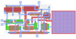
Integrated circuit design, or IC design, is a subset of electronics engineering, encompassing the particular logic and circuit design techniques required to design integrated circuits, or ICs. ICs consist of miniaturized electronic components built into an electrical network on a monolithic semiconductor substrate by photolithography.
Knowledge-based engineering (KBE) is the application of knowledge-based systems technology to the domain of manufacturing design and production. The design process is inherently a knowledge-intensive activity, so a great deal of the emphasis for KBE is on the use of knowledge-based technology to support computer-aided design (CAD) however knowledge-based techniques can be applied to the entire product lifecycle.

Microfabrication is the process of fabricating miniature structures of micrometre scales and smaller. Historically, the earliest microfabrication processes were used for integrated circuit fabrication, also known as "semiconductor manufacturing" or "semiconductor device fabrication". In the last two decades microelectromechanical systems (MEMS), microsystems, micromachines and their subfields, microfluidics/lab-on-a-chip, optical MEMS, RF MEMS, PowerMEMS, BioMEMS and their extension into nanoscale have re-used, adapted or extended microfabrication methods. Flat-panel displays and solar cells are also using similar techniques.

Technology computer-aided design is a branch of electronic design automation that models semiconductor fabrication and semiconductor device operation. The modeling of the fabrication is termed Process TCAD, while the modeling of the device operation is termed Device TCAD. Included are the modelling of process steps, and modelling of the behavior of the electrical devices based on fundamental physics, such as the doping profiles of the devices. TCAD may also include the creation of compact models, which try to capture the electrical behavior of such devices but do not generally derive them from the underlying physics.

Semiconductor process simulation is the modeling of the fabrication of semiconductor devices such as transistors. It is a branch of electronic design automation, and part of a sub-field known as technology CAD, or TCAD.

The following outline is provided as an overview of and topical guide to automation:
Post-silicon validation and debug is the last step in the development of a semiconductor integrated circuit.
Digital Prototyping gives conceptual design, engineering, manufacturing, and sales and marketing departments the ability to virtually explore a complete product before it's built. Industrial designers, manufacturers, and engineers use Digital Prototyping to design, iterate, optimize, validate, and visualize their products digitally throughout the product development process. Innovative digital prototypes can be created via CAutoD through intelligent and near-optimal iterations, meeting multiple design objectives, identifying multiple figures of merit, and reducing development gearing and time-to-market. Marketers also use Digital Prototyping to create photorealistic renderings and animations of products prior to manufacturing. Companies often adopt Digital Prototyping with the goal of improving communication between product development stakeholders, getting products to market faster, and facilitating product innovation.
Enterprise test software (ETS) is a type of software that electronics and other manufacturers use to standardize product testing enterprise-wide, rather than simply in the test engineering department. It is designed to integrate and synchronize test systems to other enterprise functions such as research and development (R&D), new product introduction (NPI), manufacturing, and supply chain, overseeing the collaborative test processes between engineers and managers in their respective departments.
Manufacturing execution systems (MES) are computerized systems used in manufacturing to track and document the transformation of raw materials to finished goods. MES provides information that helps manufacturing decision makers understand how current conditions on the plant floor can be optimized to improve production output. MES works in real time to enable the control of multiple elements of the production process.
Business process management (BPM) is a discipline in operations management in which people use various methods to discover, model, analyze, measure, improve, optimize, and automate business processes. Any combination of methods used to manage a company's business processes is BPM. Processes can be structured and repeatable or unstructured and variable. Though not required, enabling technologies are often used with BPM.
Plant Simulation is a computer application developed by Siemens PLM Software for modeling, simulating, analyzing, visualizing and optimizing production systems and processes, the flow of materials and logistic operations. Using Tecnomatix Plant Simulation, users can optimize material flow, resource utilization and logistics for all levels of plant planning from global production facilities, through local plants, to specific lines. Within the Plant Design und Optimization Solution the software portfolio, to which Plant Simulation belongs, is — together with the products of the Digital Factory and of Digital Manufacturing — part of the Product Lifecycle Management Software (PLM). The application allows comparing complex production alternatives, including the immanent process logic, by means of computer simulations. Plant Simulation is used by individual production planners as well as by multi-national enterprises, primarily to strategically plan layout, control logic and dimensions of large, complex production investments. It is one of the major products that dominate that market space.
Cloud manufacturing (CMfg) is a new manufacturing paradigm developed from existing advanced manufacturing models and enterprise information technologies under the support of cloud computing, Internet of Things (IoT), virtualization and service-oriented technologies, and advanced computing technologies. It transforms manufacturing resources and manufacturing capabilities into manufacturing services, which can be managed and operated in an intelligent and unified way to enable the full sharing and circulating of manufacturing resources and manufacturing capabilities. CMfg can provide safe and reliable, high quality, cheap and on-demand manufacturing services for the whole lifecycle of manufacturing. The concept of manufacturing here refers to big manufacturing that includes the whole lifecycle of a product.
Digital manufacturing is an integrated approach to manufacturing that is centered around a computer system. The transition to digital manufacturing has become more popular with the rise in the quantity and quality of computer systems in manufacturing plants. As more automated tools have become used in manufacturing plants it has become necessary to model, simulate, and analyze all of the machines, tooling, and input materials in order to optimize the manufacturing process. Overall, digital manufacturing can be seen sharing the same goals as computer-integrated manufacturing (CIM), flexible manufacturing, lean manufacturing, and design for manufacturability (DFM). The main difference is that digital manufacturing was evolved for use in the computerized world.
Predictive engineering analytics (PEA) is a development approach for the manufacturing industry that helps with the design of complex products. It concerns the introduction of new software tools, the integration between those, and a refinement of simulation and testing processes to improve collaboration between analysis teams that handle different applications. This is combined with intelligent reporting and data analytics. The objective is to let simulation drive the design, to predict product behavior rather than to react on issues which may arise, and to install a process that lets design continue after product delivery.


