In industry, product lifecycle management (PLM) is the process of managing the entire lifecycle of a product from its inception through the engineering, design and manufacture, as well as the service and disposal of manufactured products. PLM integrates people, data, processes, and business systems and provides a product information backbone for companies and their extended enterprises.

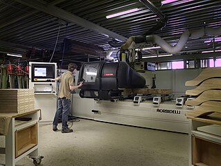
In machining, numerical control, also called computer numerical control (CNC), is the automated control of tools by means of a computer. It is used to operate tools such as drills, lathes, mills, grinders, routers and 3D printers. CNC transforms a piece of material into a specified shape by following coded programmed instructions and without a manual operator directly controlling the machining operation.

Printed circuit board milling is the milling process used for removing areas of copper from a sheet of printed circuit board (PCB) material to recreate the pads, signal traces and structures according to patterns from a digital circuit board plan known as a layout file. Similar to the more common and well known chemical PCB etch process, the PCB milling process is subtractive: material is removed to create the electrical isolation and ground planes required. However, unlike the chemical etch process, PCB milling is typically a non-chemical process and as such it can be completed in a typical office or lab environment without exposure to hazardous chemicals. High quality circuit boards can be produced using either process. In the case of PCB milling, the quality of a circuit board is chiefly determined by the system's true, or weighted, milling accuracy and control as well as the condition of the milling bits and their respective feed/rotational speeds. By contrast, in the chemical etch process, the quality of a circuit board depends on the accuracy and/or quality of the mask used to protect the copper from the chemicals and the state of the etching chemicals.

A CNC wood router is a CNC router tool that creates objects from wood. CNC stands for computer numerical control. The CNC works on the Cartesian coordinate system for 3D motion control. Parts of a project can be designed in the computer with a CAD/CAM program, and then cut automatically using a router or other cutters to produce a finished part. The CNC router is ideal for hobbies, engineering prototyping, product development, art, and production work.
Concurrent engineering (CE) or concurrent design and manufacturing is a work methodology emphasizing the parallelization of tasks, which is sometimes called simultaneous engineering or integrated product development (IPD) using an integrated product team approach. It refers to an approach used in product development in which functions of design engineering, manufacturing engineering, and other functions are integrated to reduce the time required to bring a new product to market.

FANUC is a Japanese group of companies that provide automation products and services such as robotics and computer numerical control wireless systems. These companies are principally FANUC Corporation of Japan, Fanuc America Corporation of Rochester Hills, Michigan, USA, and FANUC Europe Corporation S.A. of Luxembourg.

Computer-integrated manufacturing (CIM) is the manufacturing approach of using computers to control the entire production process. This integration allows individual processes to exchange information with each part. Manufacturing can be faster and less error-prone by the integration of computers. Typically CIM relies on closed-loop control processes based on real-time input from sensors. It is also known as flexible design and manufacturing.

Modular design, or modularity in design, is a design principle that subdivides a system into smaller parts called modules, which can be independently created, modified, replaced, or exchanged with other modules or between different systems.

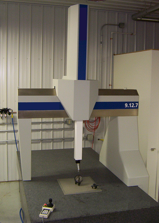
A coordinate-measuring machine (CMM) is a device that measures the geometry of physical objects by sensing discrete points on the surface of the object with a probe. Various types of probes are used in CMMs, the most common being mechanical and laser sensors, though optical and white light sensors do exist. Depending on the machine, the probe position may be manually controlled by an operator, or it may be computer controlled. CMMs(coordinate-measuring machine) specify a probe's position in terms of its displacement from a reference position in a three-dimensional Cartesian coordinate system. In addition to moving the probe along the X, Y, and Z axes, many machines also allow the probe angle to be controlled to allow measurement of surfaces that would otherwise be unreachable.

Design for manufacturability is the general engineering practice of designing products in such a way that they are easy to manufacture. The concept exists in almost all engineering disciplines, but the implementation differs widely depending on the manufacturing technology. DFM describes the process of designing or engineering a product in order to facilitate the manufacturing process in order to reduce its manufacturing costs. DFM will allow potential problems to be fixed in the design phase which is the least expensive place to address them. Other factors may affect the manufacturability such as the type of raw material, the form of the raw material, dimensional tolerances, and secondary processing such as finishing.
A flexible manufacturing system (FMS) is a manufacturing system in which there is some amount of flexibility that allows the system to react in case of changes, whether predicted or unpredicted.
Incremental sheet forming is a sheet metal forming technique where a sheet is formed into the final workpiece by a series of small incremental deformations. However, studies have shown that it can be applied to polymer and composite sheets too. Generally, the sheet is formed by a round tipped tool, typically 5 to 20mm in diameter. The tool, which can be attached to a CNC machine, a robot arm or similar, indents into the sheet by about 1 mm and follows a contour for the desired part. It then indents further and draws the next contour for the part into the sheet and continues to do this until the full part is formed. ISF can be divided into variants depending on the number of contact points between tool, sheet and die. The term Single Point Incremental Forming (SPIF) is used when the opposite side of the sheet is supported by a faceplate and Two Point Incremental Forming (TPIF) when a full or partial die supports the sheet.

STEP-NC is a machine tool control language that extends the ISO 10303 STEP standards with the machining model in ISO 14649, adding geometric dimension and tolerance data for inspection, and the STEP PDM model for integration into the wider enterprise. The combined result has been standardized as ISO 10303-238.

Hendrik (Rik) Van Brussel is a Belgian emeritus professor of mechanical engineering of the KU Leuven, world-renowned for his research on robotics, mechatronics and holonic manufacturing systems.
Cloud-based design and manufacturing (CBDM) refers to a service-oriented networked product development model in which service consumers are able to configure products or services and reconfigure manufacturing systems through Infrastructure-as-a-Service (IaaS), Platform-as-a-Service (PaaS), Hardware-as-a-Service (HaaS), and Software-as-a-Service (SaaS). Adapted from the original cloud computing paradigm and introduced into the realm of computer-aided product development, Cloud-Based Design and Manufacturing is gaining significant momentum and attention from both academia and industry.
Virtual machining is the practice of using computers to simulate and model the use of machine tools for part manufacturing. Such activity replicates the behavior and errors of a real environment in virtual reality systems. This can provide useful ways to manufacture products without physical testing on the shop floor. As a result, time and cost of part production can be decreased.

Yoram Koren is an Israeli-American academic. He is the James J. Duderstadt Distinguished University Professor Emeritus of Manufacturing and the Paul G. Goebel Professor Emeritus of Engineering at the University of Michigan, Ann Arbor. Since 2014 he is a distinguished visiting professor at the Technion – Israel Institute of Technology.
Learning factories represent a realistic manufacturing environment for education, training, and research. In the last decades, numerous learning factories have been built in academia and industry.

Ali Galip Ulsoy is an academic at the University of Michigan (UM), Ann Arbor, where he is the C.D. Mote Jr. Distinguished University Professor Emeritus of Mechanical Engineering and the William Clay Ford Professor Emeritus of Manufacturing.

Stephen Malkin was an American engineer. He taught at the University of Texas at Austin, the University at Buffalo, the University of Massachusetts Amherst, and Technion – Israel Institute of Technology.


