
A rope drive is a form of belt drive, used for mechanical power transmission.
Contents
Rope drives use a number of circular section ropes, rather than a single flat or V-belt.

A rope drive is a form of belt drive, used for mechanical power transmission.
Rope drives use a number of circular section ropes, rather than a single flat or V-belt.
The first multiple rope drive was a 9-rope drive of 200 bhp produced by Combe Barbour [1] for their Falls Foundry, Belfast, in 1863. [2] [3] James Combe experimented first with circular ropes laid from leather strips, then from manila hemp. [3] The idea of using rope drives had arisen from his earlier, 1856, experiments in using a rope drive together with an expanding vee pulley, as part of a Van Doorne or Variomatic transmission. [4] Combe Barbour were makers of textile machinery and differential speed gearing was often needed as part of the spinning process, where one shaft could be smoothly adjusted to run slightly faster or slower than another.
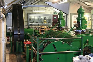
Rope drives were most widely used for power-transmission in mills and factories, where a single mill engine would have a large rope drive to each floor, where lineshafts across each floor distribute power to the individual machines. These multiple rope drives replaced the earlier technique of a vertical wrought iron shaft with bevel gears at each floor. They remained in use for as long as mills were driven by central steam engines, rather than individual electric motors. [5] Some were used with early electric motors, where these were large single motors driving a whole floor of machinery. A 1907 installation at Droylesden split the output of one motor between two floors with two new rope drives. [6] Rope drives were rarely used in the internal-combustion era, although some were used with gas engines running on producer gas. A Yorkshire mill converted to use a 1,000 hp Allen diesel engine in 1938, and retained the rope drives. [6]
Shaft drives had often used gearing from the engines to increase their speed, and thus their power transmission. This was avoided for rope drives, as the rope's maximum useful speed could be achieved from the engine's flywheel and flexibility of the ropes led to backlash in the gearing. [5]
Power transmitted was typically 50 bhp per rope, for ropes working at 5,000 feet / minute. [lower-roman 1] [5] Groups of ropes could drive different floors and they also allowed individual ropes to be replaced separately, and without losing all power to a mill floor after a rope breakage.
US practice sometimes used a single rope, looped between floors and tensioned by an idler pulley, but this system was not used in the UK and each loop was tensioned between its two pulleys by one of them being movable. Rope drives were also cheaper than belts - around a quarter of the price. [5]


The rope drives were placed in a large diagonal shaft at the side of the building, usually windowless and distinctively visible from outside the building. [lower-roman 2]
Rope drives required a larger such shaft than comparable belt or shaft drives. As the open shaft represented a channel for transmitting fires, unlike the narrow holes of a shaft drive, it needed careful fireproofing from the loom floors. [5]
It was sometimes arranged for large drives that the engine drove a set of horizontal ropes to a pulley on a layshaft or 'second motion shaft' alongside the engine house, then diagonally up through the shaft. [5]

A clutch is a mechanical device that allows the output shaft to be disconnected from the rotating input shaft. The clutch's input shaft is typically attached to a motor, while the clutch's output shaft is connected to the mechanism that does the work.
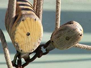
A pulley is a wheel on an axle or shaft that is designed to support movement and change of direction of a taut cable or belt, or transfer of power between the shaft and the cable or belt. In case of a pulley supported by a frame or shell that does not transfer power to a shaft, but is used to guide the cable or exert a force, the supporting shell is called a block, and the pulley may be called a sheave or pulley wheel.
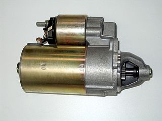
A starter is a device used to rotate (crank) an internal-combustion engine so as to initiate the engine's operation under its own power. Starters can be electric, pneumatic, or hydraulic. The starter can also be another internal-combustion engine in the case, for instance, of very large engines, or diesel engines in agricultural or excavation applications.

A stationary engine is an engine whose framework does not move. They are used to drive immobile equipment, such as pumps, generators, mills or factory machinery, or cable cars. The term usually refers to large immobile reciprocating engines, principally stationary steam engines and, to some extent, stationary internal combustion engines. Other large immobile power sources, such as steam turbines, gas turbines, and large electric motors, are categorized separately.

Variomatic is the continuously variable transmission (CVT) of the Dutch car manufacturer DAF, originally developed by Hub van Doorne. It is a stepless, fully-automatic transmission, consisting of a V-shaped drive-belt, and two pulleys, each of two cones, whose effective diameter can be changed so that the "V" belt runs nearer the spindle or nearer the rim, depending on the separation of the cones. These are synchronized so that the belt always remains at the same optimal tension.

A continuously variable transmission (CVT) is an automated transmission that can change through a continuous range of gear ratios. This contrasts with other transmissions that provide a limited number of gear ratios in fixed steps. The flexibility of a CVT with suitable control may allow the engine to operate at a constant angular velocity while the vehicle moves at varying speeds.

A sprocket, sprocket-wheel or chainwheel is a profiled wheel with teeth that mesh with a chain, track or other perforated or indented material. The name 'sprocket' applies generally to any wheel upon which radial projections engage a chain passing over it. It is distinguished from a gear in that sprockets are never meshed together directly, and differs from a pulley in that sprockets have teeth and pulleys are smooth except for timing pulleys used with toothed belts.
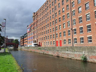
A cotton mill is a building that houses spinning or weaving machinery for the production of yarn or cloth from cotton, an important product during the Industrial Revolution in the development of the factory system.

A belt is a loop of flexible material used to link two or more rotating shafts mechanically, most often parallel. Belts may be used as a source of motion, to transmit power efficiently or to track relative movement. Belts are looped over pulleys and may have a twist between the pulleys, and the shafts need not be parallel.

A line shaft is a power-driven rotating shaft for power transmission that was used extensively from the Industrial Revolution until the early 20th century. Prior to the widespread use of electric motors small enough to be connected directly to each piece of machinery, line shafting was used to distribute power from a large central power source to machinery throughout a workshop or an industrial complex. The central power source could be a water wheel, turbine, windmill, animal power or a steam engine. Power was distributed from the shaft to the machinery by a system of belts, pulleys and gears known as millwork.
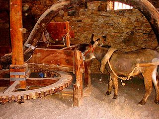
A horse mill is a mill, sometimes used in conjunction with a watermill or windmill, that uses a horse engine as the power source. Any milling process can be powered in this way, but the most frequent use of animal power in horse mills was for grinding grain and pumping water. Other animal engines for powering mills are powered by dogs, donkeys, oxen or camels. Treadwheels are engines powered by humans.
A toothed belt; timing belt; cogged belt; cog belt; or synchronous belt is a flexible belt with teeth moulded onto its inner surface. Toothed belts are usually designed to run over matching toothed pulleys or sprockets. Toothed belts are used in a wide array of mechanical devices where high power transmission is desired.
A horse engine is a machine for using draft horses to power other machinery. It is a type of animal engine that was very common before internal combustion engines and electrification. A common design for the horse engine was a large treadmill on which one or more horses walked. The surface of the treadmill was made of wooden slats linked like a chain. Rotary motion from the treadmill was first passed to a planetary gear system, and then to a shaft or pulley that could be coupled to another machine. Such powers were called tread powers, railway powers, or endless-chain powers. Another common design was the horse wheel or sweep power, in which one or several horses walked in a circle, turning a shaft at the center. Mills driven by horse powers were called horse mills. Horse engines were often portable so that they could be attached to whichever implement they were needed for at the time. Others were built into horse-engine houses.
An idler-wheel is a wheel which serves only to transmit rotation from one shaft to another, in applications where it is undesirable to connect them directly. For example, connecting a motor to the platter of a phonograph, or the crankshaft-to-camshaft gear train of an automobile.

A jackshaft, also called a countershaft, is a common mechanical design component used to transfer or synchronize rotational force in a machine. A jackshaft is often just a short stub with supporting bearings on the ends and two pulleys, gears, or cranks attached to it. In general, a jackshaft is any shaft that is used as an intermediary transmitting power from a driving shaft to a driven shaft.

The Roberts loom was a cast-iron power loom introduced by Richard Roberts in 1830. It was the first loom that was more viable than a hand loom and was easily adjustable and reliable, which led to its widespread use in the Lancashire cotton industry.
A barring engine is a small engine that forms part of the installation of a large engine, and is used to turn the main engine to a favourable position from which it can be started. If the main engine has stopped close to its dead centre it is unable to restart itself. Barring may also be done to turn the engine over slowly (unloaded) for maintenance, or to prevent belt drives being left too long in one position and taking a "set".
Urmson & Thompson was a company that manufactured stationary steam engines. It was based in Oldham, Lancashire, England. The company were general millwrights, also producing some steam engines during the 19th century and after 1904 produced large steam-driven engines for textile mills in Oldham.

A drivetrain is the group of components that deliver mechanical power from the prime mover to the driven components. In automotive engineering, the drivetrain is the components of a motor vehicle that deliver power to the drive wheels. This excludes the engine or motor that generates the power. In marine applications, the drive shaft will drive a propeller, thruster, or waterjet rather than a drive axle, while the actual engine might be similar to an automotive engine. Other machinery, equipment and vehicles may also use a drivetrain to deliver power from the engine(s) to the driven components.