SCR-268 radar

Last updated
SCR-268
SCR268-radar-guadalcanal-19420807.jpg
SCR-268 radar deployed on Guadalcanal in August 1942
Country of origin United States
Introduced1940
Type2D air-search
Frequency205 MHz
Pulsewidth7 to 15 microseconds
Range22.7 miles (36.5 km)
Power50 kW peak

The SCR-268 (for Signal Corps Radio no. 268) was the United States Army's first radar system. Introduced in 1940, it was developed to provide accurate aiming information for antiaircraft artillery and was also used for gun laying systems and directing searchlights against aircraft. The radar was widely utilized by both Army and Marine Corps air defense and early warning units during World War II. By the end of World War II the system was already considered out of date, having been replaced by the much smaller and more accurate SCR-584 microwave-based system.

Contents

Three soldiers of the United States Army operate a radar used by the 90th Coast Artillery (Antiaircraft, Semimobile, Colored) in Casablanca "Three soldiers of the United States Army sit in place at a radar used by the 90th Coast Artillery in Casablanca, French - NARA - 531325.tif
Three soldiers of the United States Army operate a radar used by the 90th Coast Artillery (Antiaircraft, Semimobile, Colored) in Casablanca

Development

The Signal Corps had been experimenting with some radar concepts as early at the late 1920s, under the direction of Colonel William R. Blair, director of the Signal Corps Laboratories at Fort Monmouth, New Jersey. While most of the Corps' efforts revolved around infra-red detection systems (a popular idea at the time), as well as a newer generation of sound detectors, they also maintained a small program of research on microwave radars based on the "beat principle", in which an aircraft would cause two signals to interfere. Low generator efficiency and a lack of ranging capability made these efforts impractical.

In 1935 one of Blair's recent arrivals, Roger B. Colton, convinced him to send an engineer to investigate the US Navy's CXAM radar project. The navy's system traced its development from experiments conducted by Albert H. Taylor and Leo C. Young at the United States Naval Research Laboratory in the early 1920s. William D. Hershberger duly went to see what they had, and returned an extremely positive report. They decided to try to find a need for such a unit in order to gain funding, and eventually received a "request" by the Chief of Coast Artillery on February 1, 1936 for a gunlaying system with a range of 15,000 yards through rain, mist, smoke or fog.

Gaining the support of James B. Allison, the Chief Signal Officer, they managed to gather a small amount of funding and "stole" some more from other projects. By December 1936 they had a working prototype, which they continued to work on and improve. On May 26, 1937 they were able to show the prototype in a convincing demonstration. After failing to find their target Martin B-10 bomber where it was supposed to be, they started "hunting" for it and found it 10 miles off course. The radar fed pointing data to a team operating a searchlight, and when it was turned on the bomber was seen to be centered in the beam. It was later learned that the target had been blown off course, making the demonstration all the more impressive.

Development of this system was slowed to some degree when a long range early-warning radar became a higher priority and parts of the prototype were salvaged for the SCR-270 they were building. Nevertheless, the system entered production at Western Electric about the same time as the -270 in 1939. The radar entered service in 1940, and about 3100 were produced by the end of the war.

Description

Oscilloscope operators with range scope at left, azimuth scope in middle, and the elevation scope at right Oscilloscope operators on an SCR 268 radar maintain watch near Menella, Italy, WWII (39728909704).jpg
Oscilloscope operators with range scope at left, azimuth scope in middle, and the elevation scope at right

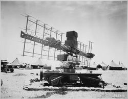
The SCR-268 antenna system consisted of a number of dipole elements arranged in three groups, each in front of a passive reflector, mounted on a large aimable cross. The cross consisted of a short upright pedestal sitting on top of a large base platform, mounting long cross-arms extending from the midpoint of the upright pedestal. The antenna system was about forty feet wide and ten feet high overall. Both the pedestal and the cross-arm could be rotated around their axis for aiming, in azimuth and altitude respectively.

The left side of the cross arm, as seen from the back, contained a set of dipoles that were set to be sensitive in angle, while almost insensitive to elevation. It was arranged six dipoles wide and four dipoles high, each with its own reflector. On the far right side was a similar, but smaller, arrangement rotated 90 degrees in order to be sensitive in elevation and not angle. This portion was two dipoles wide and six dipoles high with corresponding reflectors. Finally in the "middle" of the cross, between the upright pedestal and the elevation antenna, was the broadcasting array which created a circular beam about 10 degrees wide.

The three radar operators sat at consoles mounted on the pedestal just below the antenna cross-arm, each with their own oscilloscope display. One controlled the azimuth, another the elevation, and the third measured the range. Pointing the antenna was controlled by rotating large handwheels, the range being reported by a similar wheel.

The accuracy of the antennas themselves was not very high, about 9-12 degrees, so simply rotating the antenna and looking for a maximum would not point it very accurately. To help with this the antennas were deliberately designed to have two directions of high sensitivity, or "lobes". Signals from both lobes were displayed, slightly separated, on the layer's displays. By adjusting the antenna until the returns from both were equally strong, accuracies of about one degree were possible.

Range information was taken from the elevation array, and worked, as it did for most radars of the era, by triggering the trace on an "A-line" oscilloscope and read against a scale at the bottom. A second blip was also generated by equipment attached to the rangefinder's handwheel. By rotating the handwheel until the reference blip overlapped the one returned from the antenna, the timing could be read from the wheel. Range accuracy was about plus or minus 200 yards.

The system also included two sets of "repeaters" that sent the directional information to a searchlight, and both the directional and range (as dialed in on the rangefinder's handwheel) to a gun. The accuracy was not enough for direct gunlaying, but in combination with a searchlight the gun's existing optical equipment could "fine tune" the radar's guidance.

The radar operated at 205 MHz with a PRF of 4098 pulses per second of 6 μS (microsecond) duration, with an inter-pulse time of 240 μS. Radio waves (light) travel at about 0.093 miles/μS round-trip, so the system had a 22 miles (35 km) maximum range (240 × 0.093). It broadcast about 75 kW of power, which was, in theory, more than enough to offer longer range.

The radar was mobile, requiring four prime movers for support. Two towed the radar base and the antennas themselves, another pulled a K-34 trailer van providing power, and the fourth a van that converted the power to high voltage for the radio equipment. In total, including the trucks, the SCR-268 weighed 82,315 pounds. That the system was mobile at all was more a testament to the US's overwhelming industrial might than any quality of the radar itself.

The SCR-268 was combined with the Sperry M-4 gun director to create automatic radar-controlled gun laying; however, the relatively long wavelength (1.5 meters) resulted in poor accuracy. This system was eclipsed by the SCR-584, which utilized a 3 GHz magnetron oscillator from Britain, completely automatic tracking, and the Bell Telephone Laboratories electronic M-9 gun director. [1]

The SCR-268 was one of the first radar sets to use lobe switching of its receiving antennas as a means to locate AA (anti-aircraft) searchlight beams on aircraft. Since it did not lobe-switch its transmitted signal it would be classed as one of the first LORO (lobe-on-receive-only) radars.

Surviving examples

There are no known surviving examples of this array.

See also

Notes

  1. Mindell, David A., "Automation's Finest Hour", IEEE Control Systems Magazine 15(6)

Related Research Articles

Reflective array antenna

In telecommunications and radar, a reflective array antenna is a class of directive antennas in which multiple driven elements are mounted in front of a flat surface designed to reflect the radio waves in a desired direction. They are a type of array antenna. They are often used in the VHF and UHF frequency bands. VHF examples are generally large and resemble a highway billboard, so they are sometimes called billboard antennas. Other names are bedspring array and bowtie array depending on the type of elements making up the antenna. The curtain array is a larger version used by shortwave radio broadcasting stations.

<span class="mw-page-title-main">SCR-270</span> Early U.S. Army radar type that detected Pearl Harbor attack

The SCR-270 was one of the first operational early-warning radars. It was the U.S. Army's primary long-distance radar throughout World War II and was deployed around the world. It is also known as the Pearl Harbor Radar, since it was an SCR-270 set that detected the incoming raid about 45 minutes before the December 7, 1941, attack on Pearl Harbor commenced.

Würzburg radar Ground-based gun laying radar for the Wehrmachts Luftwaffe and German Army during World War II

The low-UHF band Würzburg radar was the primary ground-based gun laying radar for the Wehrmacht's Luftwaffe and Heer during World War II. Initial development took place before the war and the apparatus entered service in 1940. Eventually, over 4,000 Würzburgs of various models were produced. It took its name from the city of Würzburg.

Conical scanning System used in radar to improve accuracy

Conical scanning is a system used in early radar units to improve their accuracy, as well as making it easier to steer the antenna properly to point at a target. Conical scanning is similar in concept to the earlier lobe switching concept used on some of the earliest radars, and many examples of lobe switching sets were modified in the field to conical scanning during World War II, notably the German Würzburg radar. Antenna guidance can be made entirely automatic, as in the American SCR-584. Potential failure modes and susceptibility to deception jamming led to the replacement of conical scan systems with monopulse radar sets. They are still used by the Deep Space Network for maintaining communications links to space probes. The spin-stabilized Pioneer 10 and Pioneer 11 probes used onboard conical scanning maneuvers to track Earth in its orbit.

Lobe switching is a method used on early radar sets to improve tracking accuracy. It uses two slightly separated antenna elements to send the beam slightly to either side of the midline of the antenna. The radar signal switched between the two and produced two "blips" on the display. By comparing the lengths of the blips, the operator could find which one gave the stronger return, thereby indicating which direction the antenna should be moved to point directly at the target. The concept was used only briefly, and was almost completely replaced by conical scanning systems by the end of World War II. The concept is also infrequently referred to as sequential lobing, particularly when the signal steps between several different angles rather than just two.

Monopulse radar is a radar system that uses additional encoding of the radio signal to provide accurate directional information. The name refers to its ability to extract range and direction from a single signal pulse.

SCR-584 radar Automatic tracking microwave radar.

The SCR-584 was an automatic-tracking microwave radar developed by the MIT Radiation Laboratory during World War II. It was one of the most advanced ground-based radars of its era, and became one of the primary gun laying radars used worldwide well into the 1950s. A trailer-mounted mobile version was the SCR-784.

Project Diana 1946 US Army Signal Corps experiment to reflect radar signals off of the Moon

Project Diana, named for the Roman moon goddess Diana, was an experimental project of the US Army Signal Corps in 1946 to bounce radar signals off the Moon and receive the reflected signals. This was the first experiment in radar astronomy and the first active attempt to probe another celestial body. It was the inspiration for later EME (Earth-Moon-Earth) communication techniques.

Radar display Electronic device

A radar display is an electronic device to present radar data to the operator. The radar system transmits pulses or continuous waves of electromagnetic radiation, a small portion of which backscatter off targets and return to the radar system. The receiver converts all received electromagnetic radiation into a continuous electronic analog signal of varying voltage that can be converted then to a screen display.

<span class="mw-page-title-main">Signal Corps Radio</span> U.S. Army radio systems

Signal Corps Radios were U.S. Army military communications components that comprised "sets". Under the Army Nomenclature System, the abbreviation SCR initially designated "Set, Complete Radio", but was later misinterpreted as "Signal Corps Radio."

Signal Corps Laboratories (SCL) was formed on June 30, 1930, as part of the U.S. Army Signal Corps at Fort Monmouth, New Jersey. Through the years, the SCL had a number of changes in name, but remained the operation providing research and development services for the Signal Corps.

Radar in World War II greatly influenced many important aspects of the conflict. This revolutionary new technology of radio-based detection and tracking was used by both the Allies and Axis powers in World War II, which had evolved independently in a number of nations during the mid 1930s. At the outbreak of war in September 1939, both Great Britain and Germany had functioning radar systems. In Great Britain, it was called RDF, Range and Direction Finding, while in Germany the name Funkmeß (radio-measuring) was used, with apparatuses called Funkmessgerät . By the time of the Battle of Britain in mid-1940, the Royal Air Force (RAF) had fully integrated RDF as part of the national air defence.

Curtain array Class of large multielement directional wire radio transmitting antennas

Curtain arrays are a class of large multielement directional radio transmitting wire antennas, used in the shortwave radio bands. They are a type of reflective array antenna, consisting of multiple wire dipole antennas, suspended in a vertical plane, often in front of a "curtain" reflector made of a flat vertical screen of many long parallel wires. These are suspended by support wires strung between pairs of tall steel towers, up to 90 m high. They are used for long-distance skywave transmission; they transmit a beam of radio waves at a shallow angle into the sky just above the horizon, which is reflected by the ionosphere back to Earth beyond the horizon. Curtain antennas are mostly used by international short wave radio stations to broadcast to large areas at transcontinental distances.

GL Mk. I radar

Radar, Gun Laying, Mark I, or GL Mk. I for short, was an early radar system developed by the British Army to provide range information to associated anti-aircraft artillery. There were two upgrades to the same basic system, GL/EF and GL Mk. II, both of which added the ability to accurately determine bearing and elevation.

Radar, Anti-Aircraft No. 3 Mk. 7 Mobile anti-aircraft gun

Radar, Anti-Aircraft Number 3 Mark 7, also widely referred to by its development rainbow code Blue Cedar, was a mobile anti-aircraft gun laying radar designed by British Thomson-Houston (BTH) in the mid-1940s. It was used extensively by the British Army and was exported to countries such as Holland, Switzerland, Sweden Finland and South Africa. In British service, it was used with the 5.25 inch and QF 3.7 inch AA guns, as well as the Brakemine missile.

<span class="mw-page-title-main">GL Mk. III radar</span>

Radar, Gun Laying, Mark III, or GL Mk. III for short, was a radar system used by the British Army to directly guide, or lay, anti-aircraft artillery (AA). The GL Mk. III was not a single radar, but a family of related designs that saw constant improvement during and after World War II. These were renamed shortly after their introduction in late 1942, becoming the Radar, AA, No. 3, and often paired with an early warning radar, the AA No. 4, which was also produced in several models.

German Luftwaffe and Navy Kriegsmarine Radar Equipment during World War II, relied on an increasingly diverse array of communications, IFF and RDF equipment for its function. Most of this equipment received the generic prefix FuG, meaning "radio equipment". During the war, Germany renumbered their radars. From using the year of introduction as their number they moved to a different numbering scheme.

Type 277 radar

The Type 277 was a surface search and secondary aircraft early warning radar used by the Royal Navy and allies during World War II and the post-war era. It was a major update of the earlier Type 271 radar, offering much more power, better signal processing, new displays, and new antennas with greatly improved performance and much simpler mounting requirements. It allowed a radar with performance formerly found only on cruisers and battleships to be fitted even to the smallest corvettes. It began to replace the 271 in 1943 and was widespread by the end of the year.

Searchlight Control radar

Searchlight Control, SLC for short but nicknamed "Elsie", was a British Army VHF-band radar system that provided aiming guidance to an attached searchlight. By combining a searchlight with a radar, the radar did not have to be particularly accurate, it only had to be good enough to get the searchlight beam on the target. Once the target was lit, normal optical instruments could be used to guide the associated anti-aircraft artillery. This allowed the radar to be much smaller, simpler and less expensive than a system with enough accuracy to directly aim the guns, like the large and complex GL Mk. II radar. In 1943 the system was officially designated Radar, AA, No. 2, although this name is rarely used.

<span class="mw-page-title-main">SCR-602</span>

The SCR-602 also known as the AN/TPS-3, was a mobile, lightweight, medium-range, early-warning radar utilized by the United States and its allies during World War II. The radar was originally designed for use during the initial stages of an amphibious assault or military operation where its lightweight relative to other radar systems was a distinct advantage. Once larger radars such as the SCR-270 or AN/TPS-1 came online the SCR-602 could also be used to fill in gaps in radar coverage.

References