
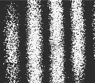
Diffraction is the deviation of waves from straight-line propagation due to an obstacle or through an aperture. The diffracting object or aperture effectively becomes a secondary source of the propagating wave. Diffraction is the same physical effect as interference, but interference is typically applied to superposition of a few waves and the term diffraction is used when many waves are superposed.

Microscopy is the technical field of using microscopes to view objects and areas of objects that cannot be seen with the naked eye. There are three well-known branches of microscopy: optical, electron, and scanning probe microscopy, along with the emerging field of X-ray microscopy.

Optics is the branch of physics that studies the behaviour and properties of light, including its interactions with matter and the construction of instruments that use or detect it. Optics usually describes the behaviour of visible, ultraviolet, and infrared light. Light is a type of electromagnetic radiation, and other forms of electromagnetic radiation such as X-rays, microwaves, and radio waves exhibit similar properties.
The focal length of an optical system is a measure of how strongly the system converges or diverges light; it is the inverse of the system's optical power. A positive focal length indicates that a system converges light, while a negative focal length indicates that the system diverges light. A system with a shorter focal length bends the rays more sharply, bringing them to a focus in a shorter distance or diverging them more quickly. For the special case of a thin lens in air, a positive focal length is the distance over which initially collimated (parallel) rays are brought to a focus, or alternatively a negative focal length indicates how far in front of the lens a point source must be located to form a collimated beam. For more general optical systems, the focal length has no intuitive meaning; it is simply the inverse of the system's optical power.
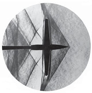
Schlieren photography is a process for photographing fluid flow. Invented by the German physicist August Toepler in 1864 to study supersonic motion, it is widely used in aeronautical engineering to photograph the flow of air around objects.
In optics, the Fraunhofer diffraction equation is used to model the diffraction of waves when plane waves are incident on a diffracting object, and the diffraction pattern is viewed at a sufficiently long distance from the object, and also when it is viewed at the focal plane of an imaging lens. In contrast, the diffraction pattern created near the diffracting object and is given by the Fresnel diffraction equation.

The point spread function (PSF) describes the response of a focused optical imaging system to a point source or point object. A more general term for the PSF is the system's impulse response; the PSF is the impulse response or impulse response function (IRF) of a focused optical imaging system. The PSF in many contexts can be thought of as the shapeless blob in an image that should represent a single point object. We can consider this as a spatial impulse response function. In functional terms, it is the spatial domain version of the optical transfer function (OTF) of an imaging system. It is a useful concept in Fourier optics, astronomical imaging, medical imaging, electron microscopy and other imaging techniques such as 3D microscopy and fluorescence microscopy.
Particle image velocimetry (PIV) is an optical method of flow visualization used in education and research. It is used to obtain instantaneous velocity measurements and related properties in fluids. The fluid is seeded with tracer particles which, for sufficiently small particles, are assumed to faithfully follow the flow dynamics. The fluid with entrained particles is illuminated so that particles are visible. The motion of the seeding particles is used to calculate speed and direction of the flow being studied.
Phase-contrast imaging is a method of imaging that has a range of different applications. It measures differences in the refractive index of different materials to differentiate between structures under analysis. In conventional light microscopy, phase contrast can be employed to distinguish between structures of similar transparency, and to examine crystals on the basis of their double refraction. This has uses in biological, medical and geological science. In X-ray tomography, the same physical principles can be used to increase image contrast by highlighting small details of differing refractive index within structures that are otherwise uniform. In transmission electron microscopy (TEM), phase contrast enables very high resolution (HR) imaging, making it possible to distinguish features a few Angstrom apart.

Photoacoustic imaging or optoacoustic imaging is a biomedical imaging modality based on the photoacoustic effect. Non-ionizing laser pulses are delivered into biological tissues and part of the energy will be absorbed and converted into heat, leading to transient thermoelastic expansion and thus wideband ultrasonic emission. The generated ultrasonic waves are detected by ultrasonic transducers and then analyzed to produce images. It is known that optical absorption is closely associated with physiological properties, such as hemoglobin concentration and oxygen saturation. As a result, the magnitude of the ultrasonic emission, which is proportional to the local energy deposition, reveals physiologically specific optical absorption contrast. 2D or 3D images of the targeted areas can then be formed.

In signal processing, apodization is the modification of the shape of a mathematical function. The function may represent an electrical signal, an optical transmission, or a mechanical structure. In optics, it is primarily used to remove Airy disks caused by diffraction around an intensity peak, improving the focus.

High-intensity focused ultrasound (HIFU), or MR-guided focused ultrasound surgery, is an incisionless therapeutic technique that uses non-ionizing ultrasonic waves to heat or ablate tissue. HIFU can be used to increase the flow of blood or lymph or to destroy tissue, such as tumors, via thermal and mechanical mechanisms. Given the prevalence and relatively low cost of ultrasound generation mechanisms, the premise of HIFU is that it is expected to be a non-invasive and low-cost therapy that can at least outperform care in the operating room.

Phased array ultrasonics (PA) is an advanced method of ultrasonic testing that has applications in medical imaging and industrial nondestructive testing. Common applications are to noninvasively examine the heart or to find flaws in manufactured materials such as welds. Single-element probes, known technically as monolithic probes, emit a beam in a fixed direction. To test or interrogate a large volume of material, a conventional probe must be physically scanned to sweep the beam through the area of interest. In contrast, the beam from a phased array probe can be focused and swept electronically without moving the probe. The beam is controllable because a phased array probe is made up of multiple small elements, each of which can be pulsed individually at a computer-calculated timing. The term phased refers to the timing, and the term array refers to the multiple elements. Phased array ultrasonic testing is based on principles of wave physics, which also have applications in fields such as optics and electromagnetic antennae.

Acoustic levitation is a method for suspending matter in air against gravity using acoustic radiation pressure from high intensity sound waves.

A Bessel beam is a wave whose amplitude is described by a Bessel function of the first kind. Electromagnetic, acoustic, gravitational, and matter waves can all be in the form of Bessel beams. A true Bessel beam is non-diffractive. This means that as it propagates, it does not diffract and spread out; this is in contrast to the usual behavior of light, which spreads out after being focused down to a small spot. Bessel beams are also self-healing, meaning that the beam can be partially obstructed at one point, but will re-form at a point further down the beam axis.
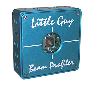
A laser beam profiler captures, displays, and records the spatial intensity profile of a laser beam at a particular plane transverse to the beam propagation path. Since there are many types of lasers—ultraviolet, visible, infrared, continuous wave, pulsed, high-power, low-power—there is an assortment of instrumentation for measuring laser beam profiles. No single laser beam profiler can handle every power level, pulse duration, repetition rate, wavelength, and beam size.
In physics, ray tracing is a method for calculating the path of waves or particles through a system with regions of varying propagation velocity, absorption characteristics, and reflecting surfaces. Under these circumstances, wavefronts may bend, change direction, or reflect off surfaces, complicating analysis.
Electronic speckle pattern interferometry (ESPI), also known as TV holography, is a technique that uses laser light, together with video detection, recording and processing, to visualise static and dynamic displacements of components with optically rough surfaces. The visualisation is in the form of fringes on the image, where each fringe normally represents a displacement of half a wavelength of the light used.

Thermoacoustic imaging was originally proposed by Theodore Bowen in 1981 as a strategy for studying the absorption properties of human tissue using virtually any kind of electromagnetic radiation. But Alexander Graham Bell first reported the physical principle upon which thermoacoustic imaging is based a century earlier. He observed that audible sound could be created by illuminating an intermittent beam of sunlight onto a rubber sheet. Shortly after Bowen's work was published, other researchers proposed methodology for thermoacoustic imaging using microwaves. In 1994 researchers used an infrared laser to produce the first thermoacoustic images of near-infrared optical absorption in a tissue-mimicking phantom, albeit in two dimensions (2D). In 1995 other researchers formulated a general reconstruction algorithm by which 2D thermoacoustic images could be computed from their "projections," i.e. thermoacoustic computed tomography (TCT). By 1998 researchers at Indiana University Medical Center extended TCT to 3D and employed pulsed microwaves to produce the first fully three-dimensional (3D) thermoacoustic images of biologic tissue [an excised lamb kidney ]. The following year they created the first fully 3D thermoacoustic images of cancer in the human breast, again using pulsed microwaves. Since that time, thermoacoustic imaging has gained widespread popularity in research institutions worldwide. As of 2008, three companies were developing commercial thermoacoustic imaging systems – Seno Medical, Endra, Inc. and OptoSonics, Inc.
Ultrasound-modulated optical tomography (UOT), also known as Acousto-Optic Tomography (AOT), is a hybrid imaging modality that combines light and sound; it is a form of tomography involving ultrasound. It is used in imaging of biological soft tissues and has potential applications for early cancer detection. As a hybrid modality which uses both light and sound, UOT provides some of the best features of both: the use of light provides strong contrast and sensitivity ; these two features are derived from the optical component of UOT. The use of ultrasound allows for high resolution, as well as a high imaging depth. However, the difficulty of tackling the two fundamental problems with UOT have caused UOT to evolve relatively slowly; most work in the field is limited to theoretical simulations or phantom / sample studies.


