This article needs additional citations for verification .(January 2008) |

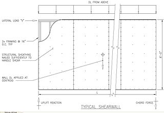
A steel plate shear wall (SPSW) consists of steel infill plates bounded by boundary elements.
This article needs additional citations for verification .(January 2008) |
A steel plate shear wall (SPSW) consists of steel infill plates bounded by boundary elements.
They constitute an SPSW. [1] Its behavior is analogous to a vertical plate girder cantilevered from its base. Similar to plate girders, the SPW system optimizes component performance by taking advantage of the post-buckling behavior of the steel infill panels. An SPW frame can be idealized as a vertical cantilever plate girder, in which the steel plates act as the web, the columns act as the flanges and the cross beams represent the transverse stiffeners. The theory that governs plate design should not be used in the design of SPW structures since the relatively high bending strength and stiffness of the beams and columns have a significant effect on the post-buckling behavior.
Capacity design of structures is: to control failure in a building by pre-selecting localized ductile fuses (or weak links) to act as the primary location for energy dissipation when a building is subjected to extreme loading. The structure is designed such that all inelastic action (or damage) occurs at these critical locations (the fuses), which are designed to behave in a ductile and stable manner. Conversely, all other structural elements are protected against failure or collapse by limiting the load transfer to these elements to the yield capacity of the fuses. In SPSWs, the infill plates are meant to serve as the fuse elements. When damaged during an extreme loading event, they can be replaced at a reasonable cost and restore the full integrity of the building. In general, SPWs are categorized based on their performance, selection of structural and load-bearing systems, and the presence of perforations or stiffeners (Table 1).
A significant amount of valuable research has been performed on the static and dynamic behavior of SPSWs. Much research has been conducted to not only help determine the behavior, response and performance of SPWs under cyclic and dynamic loading, but also as a means to help advance analysis and design methodologies for the engineering community.
The pioneering work of Kulak and co-investigators at the University of Alberta in Canada led to a simplified method for analyzing a thin unstiffened SPSW – the strip model. [2] This model is incorporated in Chapter 20 of the most recent Canadian Steel Design Standard [3] (CAN/CSA S16-01) [4] and the National Earthquake Hazard Reduction Program (NEHRP) provisions in the US.
Table 1. Categorization of steel plate walls based on performance characteristics and expectations [1]
| Performance characteristic | Performance expectations or SPW characteristics |
|---|---|
| Type of Loading carried by SPW | Lateral Load Only / Lateral Load + Wall's Dead Load (or so called 50% Gravity Load)/ Gravity + Lateral Loads |
| Structural System | Single wall with and without infill Columns / Coupled wall with and without infill Columns |
| Stiffener Spacing and Size | Post-Buckling effect can be seen in the sub panels / Panel buckles with the stiffeners globally / Stiffeners produces sub-panels which can be categorized as thick panel |
| Web Plate Behavior | Web plate yields before critical elastic buckling occurs (thick plate) / Web plate buckles elastically, develops post-buckling tension field, then yields (thin plate) |
| Web Plate Perforations | With perforations / Without perforations |
In the past two decades the steel plate shear wall (SPSW), also known as the steel plate wall (SPW), has been used in a number of buildings in Japan and North America as part of the lateral force resisting system. In earlier days, SPSWs were treated like vertically oriented plate girders and design procedures tended to be very conservative. Web buckling was prevented through extensive stiffening or by selecting an appropriately thick web plate, until more information became available on the post-buckling characteristics of web plates. Although the plate girder theory seems appropriate for the design of an SPW structure, a very important difference is the relatively high bending strength and stiffness of the beams and columns that form the boundary elements of the wall. These members are expected to have a significant effect on the overall behaviour of a building incorporating this type of system and several researchers have focused on this aspect of SPWs. The energy dissipating qualities of the web plate under extreme cyclic loading has raised the prospect of using SPSWs as a promising alternative to conventional systems in high-risk seismic regions. A further benefit is that the diagonal tension field of the web plate acts like a diagonal brace in a braced frame and thus completes the truss action, which is known to be an efficient means to control wind drift.
From a designer's point of view, steel plate walls have become a very attractive alternative to other steel systems, or to replace reinforced concrete elevator cores and shear wall. In comparative studies it has been shown that the overall costs of a building can be reduced significantly when considering the following advantages: [5]
In comparison with conventional bracing systems, steel panels have the advantage of being a redundant, continuous system exhibiting relatively stable and ductile behaviour under severe cyclic loading (Tromposch and Kulak, 1987). This benefit along with the high stiffness of the plates acting like tension braces to maintain stability, strongly qualifies the SPW as an ideal energy dissipation system in high risk seismic regions, while providing an efficient system to reduce lateral drift. Thus, some of the advantages of using SPWs compared with conventional bracing systems are as follows:
A steel plate shear element consists of steel infill plates bounded by a column-beam system. When these infill plates occupy each level within a framed bay of a structure, they constitute an SPW. Its behaviour is analogous to a vertical plate girder cantilevered from its base. Similar to plate girders, the SPW system optimizes component performance by taking advantage of the post-buckling behaviour of the steel infill panels. An SPW frame can be idealized as a vertical cantilever plate girder, in which the steel plates act as the web, the columns act as the flanges and the cross beams1 represent the transverse stiffeners. The theory that governs the design of plate girders for buildings proposed by Basler in 1960, [6] [7] should not be used in the design of SPW structures since the relatively high bending strength and stiffness of the beams and columns are expected to have a significant effect on the post-buckling behaviour. However, Basler's theory could be used as a basis to derive an analytical model for SPW systems.
Designers pioneering the use of SPWs did not have much experience nor existing data to rely upon. Typically, web plate design failed to consider post-buckling behaviour under shear, thus ignoring the advantage of the tension field and its added benefits for drift control and shear resistance. Furthermore, the inelastic deformation capacity of this highly redundant system had not been utilized, also ignoring the significant energy dissipation capability that is of great importance for buildings in high-risk seismic zones. One of the first researchers to investigate the behaviour of SPWs more closely was Kulak at the University of Alberta. Since the early 1980s, his team conducted both analytical and experimental research focused on developing design procedures suitable for drafting design standards (Driver et al., 1997, Thorburn et al., 1983, Timler and Kulak, 1983, and Tromposch and Kulak, 1987). [8] Recent research in the United States by Astaneh (2001) supports the assertion by Canadian academia that unstiffened plate, post-buckling behaviour acts as a capable shear resisting system.
There are two different modelling techniques:
The strip model represents shear panels as a series of inclined strip elements, capable of transmitting tension forces only, and oriented in the same direction as the average principal tensile stresses in the panel. By replacing a plate panel with struts, the resulting steel structure can be analyzed using currently available commercial computer analysis software. Research conducted at the University of British Columbia by Rezai et al. (1999) showed that the strip model is significantly incompatible and inaccurate for a wide range of SPW arrangements.
The strip model is limited mostly to SPSWs with thin plates (low critical buckling capacity) and certain ratios. [9] In the development of this model, no solution has been provided for a perforated SPSW, shear walls with thick steel plates and shear walls with stiffeners. The strip model concept, although appropriate for practical analysis of thin plates, is not directly applicable to other types of plates. Moreover, its implementations have yet to be incorporated in commonly used commercial computer analysis software.
In order to overcome this limitation, a general method was developed for the analysis and design of SPWs within different configurations, including walls with or without openings, with thin or thick plates, and with or without stiffeners. [10] This method considers the behavior of the steel plate and frame separately, and accounts for the interaction of these two elements, which leads to a more rational engineering design of an SPSW system. However, this model has serious shortcomings when the flexural behavior of an SPSW needs to be properly accounted for, such as the case of a slender tall building.
Modified Plate-Frame Interaction (M-PFI) model is based upon an existing shear model originally presented by Roberts and Sabouri-Ghomi (1992). Sabouri-Ghomi, Ventura and Kharrazi (2005) further refined the model and named it the Plate-Frame Interaction (PFI) model. In this paper, the PFI analytical model is then further enhanced by ‘modifying’ the load-displacement diagram to include the effect of overturning moments on the SPW response, hence the given name of the M-PFI model. [11] [12] [13] The method also addresses bending and shear interactions of the plastic ultimate capacity of steel panels, as well as bending and shear interactions of the ultimate yield strength for each individual component, that is the steel plate and surrounding frame.

A curtain wall is an exterior covering of a building in which the outer walls are non-structural, instead serving to protect the interior of the building from the elements. Because the curtain wall façade carries no structural load beyond its own dead load weight, it can be made of lightweight materials. The wall transfers lateral wind loads upon it to the main building structure through connections at floors or columns of the building.

Seismic retrofitting is the modification of existing structures to make them more resistant to seismic activity, ground motion, or soil failure due to earthquakes. With better understanding of seismic demand on structures and with recent experiences with large earthquakes near urban centers, the need of seismic retrofitting is well acknowledged. Prior to the introduction of modern seismic codes in the late 1960s for developed countries and late 1970s for many other parts of the world, many structures were designed without adequate detailing and reinforcement for seismic protection. In view of the imminent problem, various research work has been carried out. State-of-the-art technical guidelines for seismic assessment, retrofit and rehabilitation have been published around the world – such as the ASCE-SEI 41 and the New Zealand Society for Earthquake Engineering (NZSEE)'s guidelines. These codes must be regularly updated; the 1994 Northridge earthquake brought to light the brittleness of welded steel frames, for example.
In structural engineering, a shear wall is a two-dimensional vertical element of a system that is designed to resist in-plane lateral forces, typically wind and seismic loads.

A plate girder bridge is a bridge supported by two or more plate girders.
Earthquake engineering is an interdisciplinary branch of engineering that designs and analyzes structures, such as buildings and bridges, with earthquakes in mind. Its overall goal is to make such structures more resistant to earthquakes. An earthquake engineer aims to construct structures that will not be damaged in minor shaking and will avoid serious damage or collapse in a major earthquake. A properly engineered structure does not necessarily have to be extremely strong or expensive. It has to be properly designed to withstand the seismic effects while sustaining an acceptable level of damage.
This is an alphabetical list of articles pertaining specifically to structural engineering. For a broad overview of engineering, please see List of engineering topics. For biographies please see List of engineers.

Anchor bolts are used to connect structural and non-structural elements to concrete. The connection can be made by a variety of different components: anchor bolts, steel plates, or stiffeners. Anchor bolts transfer different types of load: tension forces and shear forces.
Glass fibre reinforced concrete (GFRC) is a type of fibre-reinforced concrete. The product is also known as glassfibre reinforced concrete or GRC in British English. Glass fibre concretes are mainly used in exterior building façade panels and as architectural precast concrete. Somewhat similar materials are fibre cement siding and cement boards.

Earthquake-resistant or aseismic structures are designed to protect buildings to some or greater extent from earthquakes. While no structure can be entirely impervious to earthquake damage, the goal of earthquake engineering is to erect structures that fare better during seismic activity than their conventional counterparts. According to building codes, earthquake-resistant structures are intended to withstand the largest earthquake of a certain probability that is likely to occur at their location. This means the loss of life should be minimized by preventing collapse of the buildings for rare earthquakes while the loss of the functionality should be limited for more frequent ones.

Cold-formed steel (CFS) is the common term for steel products shaped by cold-working processes carried out near room temperature, such as rolling, pressing, stamping, bending, etc. Stock bars and sheets of cold-rolled steel (CRS) are commonly used in all areas of manufacturing. The terms are opposed to hot-formed steel and hot-rolled steel.

Structural engineering depends upon a detailed knowledge of loads, physics and materials to understand and predict how structures support and resist self-weight and imposed loads. To apply the knowledge successfully structural engineers will need a detailed knowledge of mathematics and of relevant empirical and theoretical design codes. They will also need to know about the corrosion resistance of the materials and structures, especially when those structures are exposed to the external environment.
The Ship and Offshore Structural Mechanics Laboratory (SSML) is a laboratory in the Department of Naval Architecture and Ocean Engineering of Pusan National University. The SSML develops methods useful for strength analysis and structural design of marine structures. The methods developed should be helpful for achievement of high performance of the structural system. The Laboratory has the facilities for numerical and experimental studies. This includes mechanical testing equipment and high-speed computers with non-linear finite element programmes.
A buckling-restrained brace (BRB) is a structural brace in a building, designed to allow the building to withstand cyclical lateral loadings, typically earthquake-induced loading. It consists of a slender steel core, a concrete casing designed to continuously support the core and prevent buckling under axial compression, and an interface region that prevents undesired interactions between the two. Braced frames that use BRBs – known as buckling-restrained braced frames, or BRBFs – have significant advantages over typical braced frames.
Mete Avni Sözen was Kettelhut Distinguished Professor of Structural Engineering at Purdue University, Indiana, United States from 1992 to 2018.
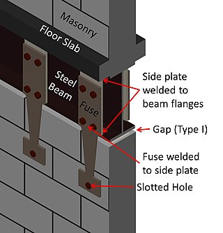
Hybrid masonry is a new type of building system that uses engineered, reinforced masonry to brace frame structures. Typically, hybrid masonry is implemented with concrete masonry panels used to brace steel frame structures. The basic concept is to attach a reinforced concrete masonry panel to a structural steel frame such that some combination of gravity forces, story shears and overturning moments can be transferred to the masonry. The structural engineer can choose from three different types of hybrid masonry and two different reinforcement anchorage types. In conventional steel frame building systems, the vertical force resisting steel frame system is supported in the lateral direction by steel bracing or an equivalent system. When the architectural plans call for concrete masonry walls to be placed within the frame, extra labor is required to ensure the masonry fits around the steel frame. Usually, this placement does not take advantage of the structural properties of the masonry panels. In hybrid masonry, the masonry panels take the place of conventional steel bracing, utilizing the structural properties of reinforced concrete masonry walls.
Moment-resisting frame is a rectilinear assemblage of beams and columns, with the beams rigidly connected to the columns.

The infill wall is the supported wall that closes the perimeter of a building constructed with a three-dimensional framework structure. Therefore, the structural frame ensures the bearing function, whereas the infill wall serves to separate inner and outer space, filling up the boxes of the outer frames. The infill wall has the unique static function to bear its own weight. The infill wall is an external vertical opaque type of closure. With respect to other categories of wall, the infill wall differs from the partition that serves to separate two interior spaces, yet also non-load bearing, and from the load bearing wall. The latter performs the same functions of the infill wall, hygro-thermically and acoustically, but performs static functions too.

Medhat Haroun was an Egyptian-American expert on earthquake engineering. He wrote more than 300 technical papers and received the Charles Martin Duke Lifeline Earthquake Engineering Award (2006) and the Walter Huber Civil Engineering Research Prize (1992) from the American Society of Civil Engineers.
This glossary of structural engineering terms pertains specifically to structural engineering and its sub-disciplines. Please see glossary of engineering for a broad overview of the major concepts of engineering.
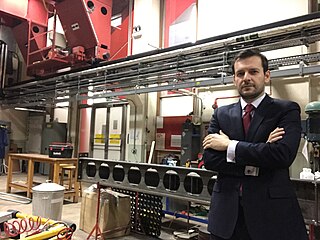
Konstantinos Daniel Tsavdaridis is a professor at the School of Civil Engineering of the University of Leeds, known for his work on lightweight steel and steel-concrete composite structures and particularly for the design of novel perforated beams and tall buildings.
Saeed Tabatabaei and Roberts (1991 and 1992), Roberts and Sabouri-Ghomi (1991 and 1992), and Berman and Bruneau (2005)