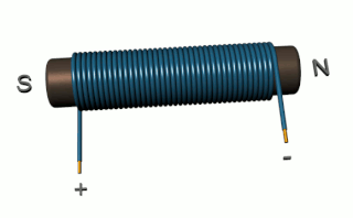
An inductor, also called a coil, choke, or reactor, is a passive two-terminal electrical component that stores energy in a magnetic field when electric current flows through it. An inductor typically consists of an insulated wire wound into a coil.

A transformer is a passive component that transfers electrical energy from one electrical circuit to another circuit, or multiple circuits. A varying current in any coil of the transformer produces a varying magnetic flux in the transformer's core, which induces a varying electromotive force (EMF) across any other coils wound around the same core. Electrical energy can be transferred between separate coils without a metallic (conductive) connection between the two circuits. Faraday's law of induction, discovered in 1831, describes the induced voltage effect in any coil due to a changing magnetic flux encircled by the coil.
The propagation constant of a sinusoidal electromagnetic wave is a measure of the change undergone by the amplitude and phase of the wave as it propagates in a given direction. The quantity being measured can be the voltage, the current in a circuit, or a field vector such as electric field strength or flux density. The propagation constant itself measures the dimensionless change in magnitude or phase per unit length. In the context of two-port networks and their cascades, propagation constant measures the change undergone by the source quantity as it propagates from one port to the next.

In electrical engineering, impedance is the opposition to alternating current presented by the combined effect of resistance and reactance in a circuit.

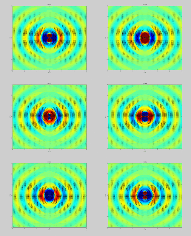
In physics, the Poynting vector represents the directional energy flux or power flow of an electromagnetic field. The SI unit of the Poynting vector is the watt per square metre (W/m2); kg/s3 in base SI units. It is named after its discoverer John Henry Poynting who first derived it in 1884. Nikolay Umov is also credited with formulating the concept. Oliver Heaviside also discovered it independently in the more general form that recognises the freedom of adding the curl of an arbitrary vector field to the definition. The Poynting vector is used throughout electromagnetics in conjunction with Poynting's theorem, the continuity equation expressing conservation of electromagnetic energy, to calculate the power flow in electromagnetic fields.

An electromagnet is a type of magnet in which the magnetic field is produced by an electric current. Electromagnets usually consist of wire wound into a coil. A current through the wire creates a magnetic field which is concentrated in the hole in the center of the coil. The magnetic field disappears when the current is turned off. The wire turns are often wound around a magnetic core made from a ferromagnetic or ferrimagnetic material such as iron; the magnetic core concentrates the magnetic flux and makes a more powerful magnet.

Inductance is the tendency of an electrical conductor to oppose a change in the electric current flowing through it. The electric current produces a magnetic field around the conductor. The magnetic field strength depends on the magnitude of the electric current, and follows any changes in the magnitude of the current. From Faraday's law of induction, any change in magnetic field through a circuit induces an electromotive force (EMF) (voltage) in the conductors, a process known as electromagnetic induction. This induced voltage created by the changing current has the effect of opposing the change in current. This is stated by Lenz's law, and the voltage is called back EMF.

A solenoid is a type of electromagnet formed by a helical coil of wire whose length is substantially greater than its diameter, which generates a controlled magnetic field. The coil can produce a uniform magnetic field in a volume of space when an electric current is passed through it.

A magnetic circuit is made up of one or more closed loop paths containing a magnetic flux. The flux is usually generated by permanent magnets or electromagnets and confined to the path by magnetic cores consisting of ferromagnetic materials like iron, although there may be air gaps or other materials in the path. Magnetic circuits are employed to efficiently channel magnetic fields in many devices such as electric motors, generators, transformers, relays, lifting electromagnets, SQUIDs, galvanometers, and magnetic recording heads.

A magnetic core is a piece of magnetic material with a high magnetic permeability used to confine and guide magnetic fields in electrical, electromechanical and magnetic devices such as electromagnets, transformers, electric motors, generators, inductors, magnetic recording heads, and magnetic assemblies. It is made of ferromagnetic metal such as iron, or ferrimagnetic compounds such as ferrites. The high permeability, relative to the surrounding air, causes the magnetic field lines to be concentrated in the core material. The magnetic field is often created by a current-carrying coil of wire around the core.
In physical systems, damping is the loss of energy of an oscillating system by dissipation. Damping is an influence within or upon an oscillatory system that has the effect of reducing or preventing its oscillation. Examples of damping include viscous damping in a fluid, surface friction, radiation, resistance in electronic oscillators, and absorption and scattering of light in optical oscillators. Damping not based on energy loss can be important in other oscillating systems such as those that occur in biological systems and bikes. Damping is not to be confused with friction, which is a type of dissipative force acting on a system. Friction can cause or be a factor of damping.

In an electric circuit, instantaneous power is the time rate of flow of energy past a given point of the circuit. In alternating current circuits, energy storage elements such as inductors and capacitors may result in periodic reversals of the direction of energy flow. Its SI unit is the watt.
The electromagnetic wave equation is a second-order partial differential equation that describes the propagation of electromagnetic waves through a medium or in a vacuum. It is a three-dimensional form of the wave equation. The homogeneous form of the equation, written in terms of either the electric field E or the magnetic field B, takes the form:
Ripple in electronics is the residual periodic variation of the DC voltage within a power supply which has been derived from an alternating current (AC) source. This ripple is due to incomplete suppression of the alternating waveform after rectification. Ripple voltage originates as the output of a rectifier or from generation and commutation of DC power.

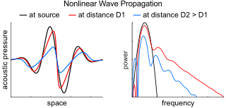
Nonlinear acoustics (NLA) is a branch of physics and acoustics dealing with sound waves of sufficiently large amplitudes. Large amplitudes require using full systems of governing equations of fluid dynamics and elasticity. These equations are generally nonlinear, and their traditional linearization is no longer possible. The solutions of these equations show that, due to the effects of nonlinearity, sound waves are being distorted as they travel.
Vector control, also called field-oriented control (FOC), is a variable-frequency drive (VFD) control method in which the stator currents of a three-phase AC or brushless DC electric motor are identified as two orthogonal components that can be visualized with a vector. One component defines the magnetic flux of the motor, the other the torque. The control system of the drive calculates the corresponding current component references from the flux and torque references given by the drive's speed control. Typically proportional-integral (PI) controllers are used to keep the measured current components at their reference values. The pulse-width modulation of the variable-frequency drive defines the transistor switching according to the stator voltage references that are the output of the PI current controllers.
In an electric power system, a harmonic of a voltage or current waveform is a sinusoidal wave whose frequency is an integer multiple of the fundamental frequency. Harmonic frequencies are produced by the action of non-linear loads such as rectifiers, discharge lighting, or saturated electric machines. They are a frequent cause of power quality problems and can result in increased equipment and conductor heating, misfiring in variable speed drives, and torque pulsations in motors and generators.
The article Ferromagnetic material properties is intended to contain a glossary of terms used to describe ferromagnetic materials, and magnetic cores.

The gyrator–capacitor model - sometimes also the capacitor-permeance model - is a lumped-element model for magnetic circuits, that can be used in place of the more common resistance–reluctance model. The model makes permeance elements analogous to electrical capacitance rather than electrical resistance. Windings are represented as gyrators, interfacing between the electrical circuit and the magnetic model.
In electromagnetism and materials science, the Jiles–Atherton model of magnetic hysteresis was introduced in 1984 by David Jiles and D. L. Atherton. This is one of the most popular models of magnetic hysteresis. Its main advantage is the fact that this model enables connection with physical parameters of the magnetic material. Jiles–Atherton model enables calculation of minor and major hysteresis loops. The original Jiles–Atherton model is suitable only for isotropic materials. However, an extension of this model presented by Ramesh et al. and corrected by Szewczyk enables the modeling of anisotropic magnetic materials.


