
In physics, physical chemistry and engineering, fluid dynamics is a subdiscipline of fluid mechanics that describes the flow of fluids—liquids and gases. It has several subdisciplines, including aerodynamics and hydrodynamics. Fluid dynamics has a wide range of applications, including calculating forces and moments on aircraft, determining the mass flow rate of petroleum through pipelines, predicting weather patterns, understanding nebulae in interstellar space and modelling fission weapon detonation.
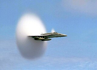
The Mach number, often only Mach, is a dimensionless quantity in fluid dynamics representing the ratio of flow velocity past a boundary to the local speed of sound. It is named after the Czech physicist and philosopher Ernst Mach.
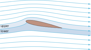
In fluid dynamics, potential flow or irrotational flow refers to a description of a fluid flow with no vorticity in it. Such a description typically arises in the limit of vanishing viscosity, i.e., for an inviscid fluid and with no vorticity present in the flow.
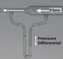
Bernoulli's principle is a key concept in fluid dynamics that relates pressure, speed and height. Bernoulli's principle states that an increase in the speed of a parcel of fluid occurs simultaneously with a decrease in either the pressure or the height above a datum. The principle is named after the Swiss mathematician and physicist Daniel Bernoulli, who published it in his book Hydrodynamica in 1738. Although Bernoulli deduced that pressure decreases when the flow speed increases, it was Leonhard Euler in 1752 who derived Bernoulli's equation in its usual form.
Compressible flow is the branch of fluid mechanics that deals with flows having significant changes in fluid density. While all flows are compressible, flows are usually treated as being incompressible when the Mach number is smaller than 0.3. The study of compressible flow is relevant to high-speed aircraft, jet engines, rocket motors, high-speed entry into a planetary atmosphere, gas pipelines, commercial applications such as abrasive blasting, and many other fields.

Transonic flow is air flowing around an object at a speed that generates regions of both subsonic and supersonic airflow around that object. The exact range of speeds depends on the object's critical Mach number, but transonic flow is seen at flight speeds close to the speed of sound, typically between Mach 0.8 and 1.2.

A de Laval nozzle is a tube which is pinched in the middle, making a carefully balanced, asymmetric hourglass shape. It is used to accelerate a compressible fluid to supersonic speeds in the axial (thrust) direction, by converting the thermal energy of the flow into kinetic energy. De Laval nozzles are widely used in some types of steam turbines and rocket engine nozzles. It also sees use in supersonic jet engines.
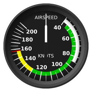
Indicated airspeed (IAS) is the airspeed of an aircraft as measured by its pitot-static system and displayed by the airspeed indicator (ASI). This is the pilots' primary airspeed reference.
In fluid dynamics, the pressure coefficient is a dimensionless number which describes the relative pressures throughout a flow field. The pressure coefficient is used in aerodynamics and hydrodynamics. Every point in a fluid flow field has its own unique pressure coefficient, Cp.
In gas dynamics, Chaplygin's equation, named after Sergei Alekseevich Chaplygin (1902), is a partial differential equation useful in the study of transonic flow. It is
In fluid dynamics, drag, sometimes referred to as fluid resistance, is a force acting opposite to the relative motion of any object, moving with respect to a surrounding fluid. This can exist between two fluid layers, two solid surfaces, or between a fluid and solid surface. Drag forces tend to decrease fluid velocity relative to the solid object in the fluid's path.
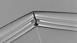
An oblique shock wave is a shock wave that, unlike a normal shock, is inclined with respect to the direction of incoming air. It occurs when a supersonic flow encounters a corner that effectively turns the flow into itself and compresses. The upstream streamlines are uniformly deflected after the shock wave. The most common way to produce an oblique shock wave is to place a wedge into supersonic, compressible flow. Similar to a normal shock wave, the oblique shock wave consists of a very thin region across which nearly discontinuous changes in the thermodynamic properties of a gas occur. While the upstream and downstream flow directions are unchanged across a normal shock, they are different for flow across an oblique shock wave.
Rayleigh flow refers to frictionless, non-adiabatic flow through a constant area duct where the effect of heat addition or rejection is considered. Compressibility effects often come into consideration, although the Rayleigh flow model certainly also applies to incompressible flow. For this model, the duct area remains constant and no mass is added within the duct. Therefore, unlike Fanno flow, the stagnation temperature is a variable. The heat addition causes a decrease in stagnation pressure, which is known as the Rayleigh effect and is critical in the design of combustion systems. Heat addition will cause both supersonic and subsonic Mach numbers to approach Mach 1, resulting in choked flow. Conversely, heat rejection decreases a subsonic Mach number and increases a supersonic Mach number along the duct. It can be shown that for calorically perfect flows the maximum entropy occurs at M = 1. Rayleigh flow is named after John Strutt, 3rd Baron Rayleigh.
In fluid dynamics, stagnation pressure is the static pressure at a stagnation point in a fluid flow. At a stagnation point the fluid velocity is zero. In an incompressible flow, stagnation pressure is equal to the sum of the free-stream static pressure and the free-stream dynamic pressure.
Choked flow is a compressible flow effect. The parameter that becomes "choked" or "limited" is the fluid velocity.
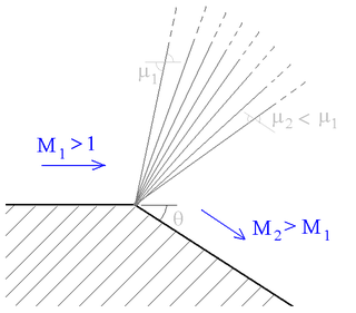
A supersonic expansion fan, technically known as Prandtl–Meyer expansion fan, a two-dimensional simple wave, is a centered expansion process that occurs when a supersonic flow turns around a convex corner. The fan consists of an infinite number of Mach waves, diverging from a sharp corner. When a flow turns around a smooth and circular corner, these waves can be extended backwards to meet at a point.
Fanno flow is the adiabatic flow through a constant area duct where the effect of friction is considered. Compressibility effects often come into consideration, although the Fanno flow model certainly also applies to incompressible flow. For this model, the duct area remains constant, the flow is assumed to be steady and one-dimensional, and no mass is added within the duct. The Fanno flow model is considered an irreversible process due to viscous effects. The viscous friction causes the flow properties to change along the duct. The frictional effect is modeled as a shear stress at the wall acting on the fluid with uniform properties over any cross section of the duct.
Isentropic nozzle flow describes the movement of a gas or fluid through a narrowing opening without an increase or decrease in entropy.
Taylor–Maccoll flow refers to the steady flow behind a conical shock wave that is attached to a solid cone. The flow is named after G. I. Taylor and J. W. Maccoll, whom described the flow in 1933, guided by an earlier work of Theodore von Kármán.
Mass injection flow refers to inviscid, adiabatic flow through a constant area duct where the effect of mass addition is considered. For this model, the duct area remains constant, the flow is assumed to be steady and one-dimensional, and mass is added within the duct. Because the flow is adiabatic, unlike in Rayleigh flow, the stagnation temperature is a constant. Compressibility effects often come into consideration, though this flow model also applies to incompressible flow.


