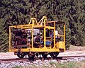
MATISA's B66 UCD, with 1200 m/h of maximum operation speed.A Plasser & Theurer 09-16 CSM Tamper / Liner
A tamping machine or ballast tamper, informally simply a tamper, is a self-propelled, rail-mounted machine used to position very precisely the track (rail and connected sleepers), by means of a lifting lining unit (or clamp), and stabilize the new position by packing (or tamping) the track ballast under railway tracks, by means of a group of mechanized tines.[1]
Prior to the introduction of mechanical tampers, this task was done by manual labour with the help of beaters. As well as being faster, more accurate, more efficient and less labour-intensive, tamping machines are essential for the use of concrete sleepers since they are too heavy (usually over 250kg or 550lb) to be lifted by hand.
At its most basic, an ancient tamping machine only packed the ballast. Practically all modern machines correct the alignment of the rails to make them parallel and level, in order to achieve a more comfortable ride for passengers and freight and to reduce the mechanical strain applied to the rails by passing trains. This is done by finding places where the sleepers have sunk from the weight of the passing trains or frost action, causing the track to sag. The tamper lifts each sleeper and the rails up, and packs ballast underneath.[2] When the sleeper is laid down again, the sagged rails now sit at the proper level. Combining tamping and alignemnt into a single machine saves time and money, as only one machine needs to be run over the track to perform both functions.
Tampers frequently work in concert with ballast regulators, as part of a section crew.
History
In the early days of railroading, the ballast was maintained by hand, with gandy dancers using shovels and beaters to move, clean, and compact ballast. Rails would be jacked up with large track jacks to allow the crews to do their work.[2] This process took quite a long time and was subject to human error.
Starting in the 1930s, automatic tools for tamping were first developed and used, though they still had to be operated by hand. In the following decades, tamping machines were developed to automate the process, using dedicated machines that travelled on the rails.[2]
In recent years, larger tamping machines have been developed that incorporate additional functions such as lining and lifting the rails on top of their tamping function. These are known in North America as production tampers.[2]
Types
A GTRM Rail Plasser and Theurer 07 rail tamping machineAn Amey Plasser and Theurer 08 rail tamping machine
Tamper machines are built in many different varieties depending on their purpose:
Plain-line tamping machines: used on line sections which have no points or other complex track structures, commonly referred to as production machines, generally have moving tamping head positions.
Switch tamping machines: used to tamp switches, crossings and other complex track structures, have movable tamping heads with ability to isolate heads when required.
Tamping process
The tamping process from any type of tamper consists of the following basic steps:[2]
The lifting, lining unit moves the rail and sleepers under the tamping unit into the desired vertical and horizontal position. At this stage, the desired position of the rails and sleeper will only be maintained as long as the lifting, lining unit holds the track in position.
The tamping units drive vibrating and oscillating tines (42Hz optimum) into the ballast on both sides of the sleeper parallel to the rails until squeezing depth is achieved. The rapidly vibrating and oscillating tines in effect liquefy the ballast to allow easy insertion of the tines.
The vibrating tines are pushed together underneath the sleeper to pack ballast underneath the sleeper being held in position by the lifting, lining unit to ensure it holds position when released by the lifting, lining unit.
The tamping unit retracts to the rest position, slightly above the top of the rails. The track and sleeper are released by the lifting, lining unit and maintain their position thanks to the modification of the ballast done in the previous step of the process.
The tamping machine moves to the next sleeper and begins a new cycle.
Standard arrangement
The basic principles and functions of a tamping machine remain the same regardless of manufacturer with only minor differences in design.
Drive
The majority of track machines are powered by a diesel engine. This provides power to the driving wheels via either a hydrostatic circuit or cardan shaft, allowing the machine to propel itself to and around a work-site. The engine also drives a hydraulic pump to provide power for the various tools.
Lifting lining unit
The lifting lining unit of a tamping machine (the clamp) lifts and holds the track in corrected position while the ballast underneath being tamped. All types of units require the following components to achieve this task:
Chassis
Normally rectangular with four wheels to ride on the rails
Lifting cylinders
One cylinder on either side connecting the unit to main machine chassis and allowing the unit to lift track vertically
Lining cylinders
Two horizontal cylinders between unit chassis and main machine chassis used to push/pull the track horizontally
Clamp or "hook" assemblies
These are usually on the outside of each rail and utilize hydraulic cylinders to clamp onto the side of the railhead so that is locked to the unit chassis before lifting and lining is commenced
The lifting lining unit is usually secured to the main machine chassis via a hydraulically length-adjustable trailing arm. The arm is adjustable so that the unit can be moved clear of small obstructions such as insulated joints or wires.
Reference system
To ensure track geometry is corrected, most tamping machines use an optical system to determine the relative position of three points of the machines, usually indicated as A, B and C. Some machines will use a fourth point between B and C to carry out quality control measurements.
A point is always the front reference point and sits on uncorrected track. B point is positioned as close as physically possible to the lifting lining unit (the clamp). B point is used by the machine control system to position the track correctly using either potentiometers or optical filters, depending on type of chord system used.
C point is the rear-most measuring point and anchorage point for lifting and lining chords. Depending on type of chord system C point will be either wire anchor with a tensioning cylinder or a photoelectric light receiver.
All three points are individual rail trolleys able to freely move up, down, left and right independent of the machine chassis and hence follow any minor fluctuation in rail position. When working, the machine uses pneumatic cylinders to lightly push these trolleys into the selected datum rail both vertically and horizontally.
When using this method, the tower operator positions A point anchorages according to existing track geometry measurements taken beforehand. Once A point has been positioned, it is then assumed that both A and C are in correct position as if machine were sitting on corrected track. The machine then uses the lifting lining unit to move the rail and B point in line with A and C.
Tamping units
System 7 fully hydraulic tamping head
The Tamping units of most Tamping machines will consist of:
A set of tines either 8 or 16 per sleeper divided evenly between front and rear of sleeper
Mounting or "guide" rods that allow the unit as a whole to move up and down in a linear motion
Support frame
Squeezing arms
Tine mounts, can be either part of the squeezing arm or attached to it via a pin to allow swiveling depending on type of tamping machine
To generate the vibration needed for penetration and consolidation there are two leading methods commonly used:
Using a hydraulically driven eccentric shaft attached either to the end of the squeezing cylinders or acting as the pivot point for the squeezing arms
Using a special squeezing cylinder and valve assembly to oscillate the tines
A less common method more often seen on tamping head attachments for excavators is to use a motor driven vibrator assembly that is directly bolted to the support frame.
Specialized machines
Continuous-action tamping machines
A continuous-action tamping machine (CAT) can pack between one and four sleepers at a time, with outputs between 320m/h and 2600m/h generally anticipated.[3]
Dynamic Tamping Express
The 'Tamping Express' is a machine developed by Plasser & Theurer, and in the UK and Europe is referred to as the 09-3X. This machine consists of a conventional CAT-style satellite with tooling for three sleepers in continuous succession, along with a full DTS stabilising unit suspended from the rear most vehicle in the machine.[4]
Tamping and cleaning operations have the adverse effect of reducing the resistance of the track to lateral movement. The resistance gradually recovers with the passage of trains, but may require a speed restriction imposed for the duration. This 'consolidation' can be achieved faster and in a more controlled manner using mechanised equipment known as the dynamic track stabiliser (DTS).
A DTS will normally be used only after a stretch of track has been tamped and aligned.
D.G.S. has a vibrating unit which holds the track in position and applies a horizontal vibration and vertical load to simulate the passage of trains. The track parameters (or cross levels), before and after stabilising, can be viewed through bogies in the front and rear.
Dynamic track stabilising has the following advantages, resulting in enhanced safety:
Increases the resistance of the track to lateral movement
Creates a homogenous bed of ballast
Permits earlier relaxation of speed restrictions
Eliminates non-uniform initial differential settlements caused by rail traffic
Retains correct track geometry for a longer period than was achievable using tamping machines alone
The stabilisation achieved by one pass of a DGS is equal to that achieved by 100,000tonnes of traffic, and allows a speed restriction of 20km/h to be relaxed to 40km/h
Dynamic stabilisation is usually avoided on bridges or around overhead structures since there is a risk of damage to foundations.
Tamping and track layouts
The appropriate tamping procedures and tamping machine depends in part on the track layout.
On plain track everything is fairly straight forward and any brand and model of machine can be used.[5]
But through tunnels and bridges with no ballast to tamp, special measures are needed to transition from the ballasted track to the unballasted track. An example would be the Glenbrook Tunnel Turnouts require a more complicated tamping machine with extra and adjustable tongs to cater for the extra rails and variable spacing of the sleepers. Similarly for dual gauge such as between Perth and Northam.
Ideally turnouts and diamond crossings should be some distance apart so the each component can be tamped without having to immediately tamp the other components. However a majority of track components are right next to each other so that these components need to be tamped as a group in multiple small stages.
Track centres determine whether one end of a crossover, consisting of two turnouts, can be tamped one at a time, with train traffic still running on the other track.
Balfour Beatty and Carillion tamping machine in the UK.
A Multiple-Tie-Tamper seen at Sagamiko Station in Sagamihara, Kanagawa, Japan.
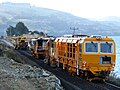
Plasser & Theurer DGS 62 N dynamic track stabilizer, followed by SSP 300 Regulator, then a Plasser 09-16 CAT Continuous Action Tamper, in Blueskin Bay, New Zealand.
This page is based on this Wikipedia article Text is available under the CC BY-SA 4.0 license; additional terms may apply. Images, videos and audio are available under their respective licenses.