
In optics, aberration is a property of optical systems, such as lenses, that causes light to be spread out over some region of space rather than focused to a point. Aberrations cause the image formed by a lens to be blurred or distorted, with the nature of the distortion depending on the type of aberration. Aberration can be defined as a departure of the performance of an optical system from the predictions of paraxial optics. In an imaging system, it occurs when light from one point of an object does not converge into a single point after transmission through the system. Aberrations occur because the simple paraxial theory is not a completely accurate model of the effect of an optical system on light, rather than due to flaws in the optical elements.
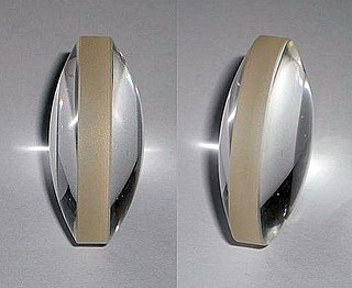
A lens is a transmissive optical device which focuses or disperses a light beam by means of refraction. A simple lens consists of a single piece of transparent material, while a compound lens consists of several simple lenses (elements), usually arranged along a common axis. Lenses are made from materials such as glass or plastic, and are ground and polished or molded to a desired shape. A lens can focus light to form an image, unlike a prism, which refracts light without focusing. Devices that similarly focus or disperse waves and radiation other than visible light are also called lenses, such as microwave lenses, electron lenses, acoustic lenses, or explosive lenses.

Optics is the branch of physics that studies the behaviour and properties of light, including its interactions with matter and the construction of instruments that use or detect it. Optics usually describes the behaviour of visible, ultraviolet, and infrared light. Because light is an electromagnetic wave, other forms of electromagnetic radiation such as X-rays, microwaves, and radio waves exhibit similar properties.

In optics, the numerical aperture (NA) of an optical system is a dimensionless number that characterizes the range of angles over which the system can accept or emit light. By incorporating index of refraction in its definition, NA has the property that it is constant for a beam as it goes from one material to another, provided there is no refractive power at the interface. The exact definition of the term varies slightly between different areas of optics. Numerical aperture is commonly used in microscopy to describe the acceptance cone of an objective, and in fiber optics, in which it describes the range of angles within which light that is incident on the fiber will be transmitted along it.
The focal length of an optical system is a measure of how strongly the system converges or diverges light; it is the inverse of the system's optical power. A positive focal length indicates that a system converges light, while a negative focal length indicates that the system diverges light. A system with a shorter focal length bends the rays more sharply, bringing them to a focus in a shorter distance or diverging them more quickly. For the special case of a thin lens in air, a positive focal length is the distance over which initially collimated (parallel) rays are brought to a focus, or alternatively a negative focal length indicates how far in front of the lens a point source must be located to form a collimated beam. For more general optical systems, the focal length has no intuitive meaning; it is simply the inverse of the system's optical power.
A dioptre or diopter is a unit of measurement of the optical power of a lens or curved mirror, which is equal to the reciprocal of the focal length measured in metres. It is thus a unit of reciprocal length. For example, a 3-dioptre lens brings parallel rays of light to focus at 1⁄3 metre. A flat window has an optical power of zero dioptres, and does not cause light to converge or diverge. Dioptres are also sometimes used for other reciprocals of distance, particularly radii of curvature and the vergence of optical beams.
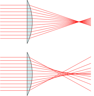
In optics, spherical aberration (SA) is a type of aberration found in optical systems that have elements with spherical surfaces. Lenses and curved mirrors are prime examples, because this shape is easier to manufacture. Light rays that strike a spherical surface off-centre are refracted or reflected more or less than those that strike close to the centre. This deviation reduces the quality of images produced by optical systems.

A collimated beam of light or other electromagnetic radiation has parallel rays, and therefore will spread minimally as it propagates. A perfectly collimated light beam, with no divergence, would not disperse with distance. However, diffraction prevents the creation of any such beam.

A reflecting telescope is a telescope that uses a single or a combination of curved mirrors that reflect light and form an image. The reflecting telescope was invented in the 17th century by Isaac Newton as an alternative to the refracting telescope which, at that time, was a design that suffered from severe chromatic aberration. Although reflecting telescopes produce other types of optical aberrations, it is a design that allows for very large diameter objectives. Almost all of the major telescopes used in astronomy research are reflectors. Reflecting telescopes come in many design variations and may employ extra optical elements to improve image quality or place the image in a mechanically advantageous position. Since reflecting telescopes use mirrors, the design is sometimes referred to as a catoptric telescope.
Optics is the branch of physics which involves the behavior and properties of light, including its interactions with matter and the construction of instruments that use or detect it. Optics usually describes the behavior of visible, ultraviolet, and infrared light. Because light is an electromagnetic wave, other forms of electromagnetic radiation such as X-rays, microwaves, and radio waves exhibit similar properties.

In optics, the coma, or comatic aberration, in an optical system refers to aberration inherent to certain optical designs or due to imperfection in the lens or other components that results in off-axis point sources such as stars appearing distorted, appearing to have a tail (coma) like a comet. Specifically, coma is defined as a variation in magnification over the entrance pupil. In refractive or diffractive optical systems, especially those imaging a wide spectral range, coma can be a function of wavelength, in which case it is a form of chromatic aberration.
In optics, the Fraunhofer diffraction equation is used to model the diffraction of waves when the diffraction pattern is viewed at a long distance from the diffracting object, and also when it is viewed at the focal plane of an imaging lens. In contrast, the diffraction pattern created near the object is given by the Fresnel diffraction equation.

In geometrical optics, a focus, also called an image point, is a point where light rays originating from a point on the object converge. Although the focus is conceptually a point, physically the focus has a spatial extent, called the blur circle. This non-ideal focusing may be caused by aberrations of the imaging optics. In the absence of significant aberrations, the smallest possible blur circle is the Airy disc, which is caused by diffraction from the optical system's aperture. Aberrations tend to worsen as the aperture diameter increases, while the Airy circle is smallest for large apertures.

In physics, the wavefront of a time-varying field is the set (locus) of all points where the wave has the same phase of the sinusoid. The term is generally meaningful only for fields that, at each point, vary sinusoidally in time with a single temporal frequency.

An aspheric lens or asphere is a lens whose surface profiles are not portions of a sphere or cylinder. In photography, a lens assembly that includes an aspheric element is often called an aspherical lens.

A spatial filter is an optical device which uses the principles of Fourier optics to alter the structure of a beam of light or other electromagnetic radiation, typically coherent laser light. Spatial filtering is commonly used to "clean up" the output of lasers, removing aberrations in the beam due to imperfect, dirty, or damaged optics, or due to variations in the laser gain medium itself. This filtering can be applied to transmit a pure transverse mode from a multimode laser while blocking other modes emitted from the optical resonator. The term "filtering" indicates that the desirable structural features of the original source pass through the filter, while the undesirable features are blocked. An apparatus which follows the filter effectively sees a higher-quality but lower-powered image of the source, instead of the actual source directly. An example of the use of spatial filter can be seen in advanced setup of micro-Raman spectroscopy.
In Gaussian optics, the cardinal points consist of three pairs of points located on the optical axis of a rotationally symmetric, focal, optical system. These are the focal points, the principal points, and the nodal points. For ideal systems, the basic imaging properties such as image size, location, and orientation are completely determined by the locations of the cardinal points; in fact only four points are necessary: the focal points and either the principal or nodal points. The only ideal system that has been achieved in practice is the plane mirror, however the cardinal points are widely used to approximate the behavior of real optical systems. Cardinal points provide a way to analytically simplify a system with many components, allowing the imaging characteristics of the system to be approximately determined with simple calculations.
In laser science, the parameter M2, also known as the beam propagation ratio or beam quality factor is a measure of laser beam quality. It represents the degree of variation of a beam from an ideal Gaussian beam. It is calculated from the ratio of the beam parameter product (BPP) of the beam to that of a Gaussian beam with the same wavelength. It relates the beam divergence of a laser beam to the minimum focussed spot size that can be achieved. For a single mode TEM00 (Gaussian) laser beam, M2 is exactly one. Unlike the beam parameter product, M2 is unitless and does not vary with wavelength.

A curved mirror is a mirror with a curved reflecting surface. The surface may be either convex or concave. Most curved mirrors have surfaces that are shaped like part of a sphere, but other shapes are sometimes used in optical devices. The most common non-spherical type are parabolic reflectors, found in optical devices such as reflecting telescopes that need to image distant objects, since spherical mirror systems, like spherical lenses, suffer from spherical aberration. Distorting mirrors are used for entertainment. They have convex and concave regions that produce deliberately distorted images. They also provide highly magnified or highly diminished (smaller) images when the object is placed at certain distances.
In optics an afocal system is an optical system that produces no net convergence or divergence of the beam, i.e. has an infinite effective focal length. This type of system can be created with a pair of optical elements where the distance between the elements is equal to the sum of each element's focal length. A simple example of an afocal optical system is an optical telescope imaging a star, the light entering the system is at infinity and the image it forms is at infinity. Although the system does not alter the divergence of a collimated beam, it does alter the width of the beam, increasing magnification. The magnification of such a telescope is given by


